Laboratory Report #1 Resistor Colour Codes and Meter
advertisement

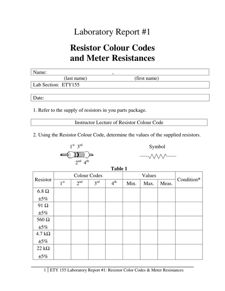
Laboratory Report #1 Resistor Colour Codes and Meter Resistances Name: , (last name) Lab Section: ETY155 (first name) Date: 1. Refer to the supply of resistors in you parts package. Instructor Lecture of Resistor Colour Code 2. Using the Resistor Colour Code, determine the values of the supplied resistors. 1st 3rd Symbol 2nd 4th Resistor Table 1 Colour Codes 1st 2nd 3rd Values 4th Min. Max. Meas. Condition* 6.8 ±5% 91 ±5% 560 ±5% 4.7 k ±5% 22 k ±5% 1 ETY 155 Laboratory Report #1: Resistor Color Codes & Meter Resistances * Resistor condition: GOOD (within tolerance), CHANGED VALUE (out of tolerance but not 0 nor infinity ohms), OPEN (infinity ohms), SHORTED (0 ohm). Instructor Demo of Ohmmeter, Voltmeter, and Ammeter 3. Using the multimeter configured as an ohmmeter, measure the given resistors and insert values in Table 1. 4. Refer to the supply of resistors indicated in Table 2. Determine what colour code you are looking for. Table 2 Resistor Colour Codes 1st 2nd 3rd Values 4th Min. Max. Meas. Condition 10 ±5% 100 ±5% 10 k ±5% 100 k ±5% 1M ±5% 5. Measure these resistors and insert their values in Table 2. Protoboard (Breadboard) Layout Instructor Demo of Protoboard Function Schematic to Pictorial 2 ETY 155 Laboratory Report #1: Resistor Color Codes & Meter Resistances 6. Using the protoboard and resistors in your parts package, connect as many resistors in series as necessary to give a total resistance which fits into the tolerance of 8.3 k ±5%. Draw the pictorial below indicating the placement (and connections) of the ohmmeter and the values of resistors used. 7. Calculate the minimum value and maximum value 8.3 k ±5% can be, then measure the actual value of this string of series resistors and insert in Table 3. Table 3 Calculated Values Minimum Maximum Measured Value 3 ETY 155 Laboratory Report #1: Resistor Color Codes & Meter Resistances 8. Using the protoboard and resistors in your parts package, connect as many resistors in series as necessary to give a total resistance which fits into the tolerance of 14.9 k ±5%. Draw the pictorial below indicating the placement of the ohmmeter and the values of resistors used. 9. Calculate the minimum value and maximum value 14.9 k ±5% can be, then measure the actual value of this string of series resistors and insert in Table 4. Table 4 Calculated Values Minimum Maximum Measured Value 4 ETY 155 Laboratory Report #1: Resistor Color Codes & Meter Resistances 10. Using one multimeter configured as an ohmmeter, and the other multimeter configured as a voltmeter, measure the resistance of all the voltmeter ranges. Insert the data in Table 5. Table 5 Voltmeter Ranges Measured Resistance 11. Using one multimeter configured as an ohmmeter, and the other multimeter configured as an ammeter, measure the resistance of all the ammeter ranges. Insert the data in Table 6. Table 6 Ammeter Ranges Measured Resistance 12. Using the resistors in your parts package configure the least number of resistors in series to result in a resistance closest to the desired values. Record in Table 7. Table 7 Total Resistance Desired 600 2.4 k 5.3 k 7k 8.5 k Resistors Used Measured Resistance The End 5 ETY 155 Laboratory Report #1: Resistor Color Codes & Meter Resistances


