Application of a Pencil Ionization Chamber
advertisement
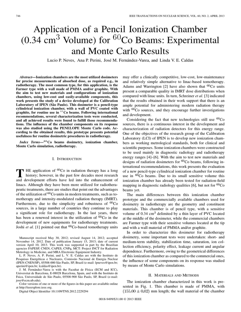
746 IEEE TRANSACTIONS ON NUCLEAR SCIENCE, VOL. 60, NO. 2, APRIL 2013 Application of a Pencil Ionization Chamber (0.34 cm3 Volume) for 60Co Beams: Experimental and Monte Carlo Results Lucio P. Neves, Ana P. Perini, José M. Fernández-Varea, and Linda V. E. Caldas Abstract—Ionization chambers are the most utilized dosimeters for precise measurements of absorbed dose, as required e.g., in radiotherapy. The most common type, for this application, is the Farmer type with a wall made of PMMA and/or graphite. With the aim to test new materials and configurations of ionization chambers, using low-cost and easily-available components, this work presents the study of a device developed at the Calibration Laboratory of IPEN (São Paulo). This dosimeter is a pencil-type cylindrical ionization chamber, with a wall of PVC coated with graphite, for routine use in 60 Co beams. Following international recommendations, several characterization tests were conducted, and all achieved results were found to fulfill those recommendations. The influence of the chamber components on its response was also studied using the PENELOPE Monte Carlo code. According to the obtained results, this prototype presents potential usefulness for routine dosimetric procedures in radiotherapy. Index Terms—60 Co beams dosimetry, ionization chamber, Monte Carlo simulation, radiotherapy. I. INTRODUCTION T HE application of Co in radiation therapy has a long history; however, in the past few decades most research and development efforts have led into the enhancement of linacs. Although they have been more utilized for radiotherapeutic treatments, there are studies that point out the advantages of the utilization of Co units in modern treatments, such as tomotherapy and intensity-modulated radiation therapy (IMRT). Furthermore, due to the simplicity and robustness of Co sources, in a large number of countries they continue to play a significant role for radiotherapy. In the last years, there has been a renewed interest in the utilization of Co in the development of new equipments for radiotherapy treatments. Joshi et al. [1] pointed out that Co-based tomotherapy units Manuscript received May 30, 2012; revised August 14, 2012; accepted November 14, 2012. Date of publication January 15, 2013; date of current version April 10, 2013. This work was supported in part by the Brazilian agencies FAPESP, CNEN, CAPES, CNPq, MCT: Project INCT for Radiation Metrology in Medicine, and MRA Electronic Equipment Industry. L. P. Neves, A. P. Perini, and L. V. E. Caldas are with the Instituto de Pesquisas Energéticas e Nucleares, Comissão Nacional de Energia Nuclear (IPEN-CNEN/SP), 05508-000 São Paulo, SP, Brazil (e-mail: lpneves@ipen.br; aperini@ipen.br; lcaldas@ipen.br). J. M. Fernández-Varea is with the Facultat de Física (ECM and ICC), Universitat de Barcelona, E-08028 Barcelona, Spain, and with the Instituto de Fs ´ ica, Universidade de São Paulo, 05508-900 São Paulo, SP, Brazil (e-mail: jose@ecm.ub.edu). Color versions of one or more of the figures in this paper are available online at http://ieeexplore.ieee.org. Digital Object Identifier 10.1109/TNS.2012.2229294 may offer a clinically competitive, low-cost, low-maintenance and relatively simple alternative to linac-based tomotherapy. Adams and Warrington [2] have also shown that Co units present a comparable quality in IMRT dose distributions when compared with linac units. In turn, Schreiner et al. [3] indicated that the results obtained in their work support that there is an ample potential for administering modern radiation therapy with Co sources, and they encourage further investigations and development. Considering the fact that new technologies still use Co sources, there is a continuous interest in the development and characterization of radiation detectors for this energy range. One of the objectives of the research group of the Calibration Laboratory (LCI) of IPEN is to develop new ionization chambers as working metrological standards, both for clinical and scientific purposes. Some ionization chambers were constructed to be used mainly in diagnostic radiology and radiotherapy energy ranges [4]–[6]. With the aim to test new materials and designs of radiation dosimeters for Co beams, following international recommendations, this work presents the evaluation of a new pencil-type cylindrical ionization chamber for routine use in Co beams. Due to its small sensitive volume this ionization chamber has already been tested for radiation-field mapping in diagnostic radiology qualities [6], but not for Co beams yet. The main differences between this ionization chamber prototype and the commercially available chambers used for dosimetry in radiotherapy are the geometry and constituent materials. This chamber is of pencil type, with a sensitive volume of 0.34 cm delimited by a thin layer of PVC located at the middle of the dosimeter, while the commercial chambers are Farmer type with their sensitive volumes located at the tip and with a wall material of PMMA and/or graphite. In order to characterize this dosimeter for radiotherapy dosimetry, some important tests were undertaken: short- and medium-term stability, stabilization time, saturation, ion collection efficiency, polarity effect, leakage current and angular dependence. Furthermore, owing to the geometrical differences of this ionization chamber as compared to the commercial ones, the influence of some components on its response was studied by means of Monte Carlo simulations. II. MATERIALS AND METHODS The ionization chamber characterized in this work is presented in Fig. 1. This chamber is made of PMMA, with mm length; the wall material of the chamber 0018-9499/$31.00 © 2013 IEEE NEVES et al.: APPLICATION OF A PENCIL IONIZATION CHAMBER FOR CO BEAMS Fig. 1. Pencil ionization chamber developed at the IPEN with a schematic representation of its sensitive volume. Fig. 2. Positioning system utilized in the angular dependence test. sensitive volume is PVC with graphite coating, and its collecting electrode material is made of aluminum, with a mm. The chamber internal diameter diameter of is mm, and its wall thickness and the sensitive mm and mm, respeclength are tively, and the ionization chamber has a sensitive volume of cm . A special build-up cap for Co beams was made of PMMA, with a thickness of mm. All experimental tests were undertaken according to international recommendations [7], using a Gammatron II S80 irradiation system ( Co source), and an electrometer, model UNIDOS E, Physikalisch-Technische Werkstätten (PTW) Freiburg, Germany. For the angular dependence test, a commercial goniometer, OPTRON, model GN1 200, and a special positioning system (Fig. 2) were employed. The irradiation conditions for all measurements were fixed at a reference field of 10 10 cm using the Co unit for 15 s. The air kerma rate mGy/s, measured with a secondary standard was ionization chamber PTW, model TN30012, with traceability to the Bureau International des Poids et Mesures (BIPM). All readings were corrected for standard environmental conditions of temperature and pressure. In this study, the Monte Carlo simulations of the ionization chamber were carried out with PENELOPE/penEasy [8], [9], a general-purpose subroutine package and main program for the coupled simulation of electron/photon transport. The ionization chamber was modeled according to its dimensions and composition, including a very detailed description of the BNC connector. This procedure was undertaken be- 747 cause normally commercial ionization chambers have the connector on the extremity of a cable, and not directly connected to the chamber, as in this case. This description of the connector will allow a more confident analysis of its influence on the energy deposited in the sensitive volume. The simulated ionization chamber and its constituent materials are shown in Fig. 3. Other geometrical parameters such as the distances and field sizes utilized during the experiments were also modeled in the simulation. The ionization chamber was positioned 100 cm from the gamma source, and there was a 5-cm-thick air layer in front and behind of the ionization chamber. The selected simulation parameters are listed in Table I. In Table I, parameters other than is cutoff energies control the electron transport mechanics: is the maximum average fracthe average angular deflection; tional energy loss between consecutive hard elastic events; is the cutoff energy loss for hard inelastic collisions and is the cutoff energy loss for hard Bremsstrahlung. The maximum cm, to switch off the external allowed step length was set to step-length control. The photon spectrum of the Gammatron II S 80 Co unit used in the experiments was not found in the literature, and the blueprints of this unit were not available either. Therefore, three photon spectra were adopted and compared, namely that of a bare source of Co and the spectra calculated by Mora et al. [10] and by Tedgren et al. [11]. In the work of Mora et al. [10] an Eldorado 6 Co unit was simulated with the BEAM-EGS4 code [12], while Tedgren et al. [11] simulated a Siemens Gammatron 1 Co unit employing BEAMnrc [13]. Both spectra were determined free in air for a 10 10 cm field size, with a source-detector distance of 100 cm. histories were simulated, and the energy deIn each run, posited in the air contained in the sensitive volume was scored. This value was then compared to the experimental results, in order to validate the simulation, and also to evaluate the influence of some components of the ionization chamber: the PMMA body, collecting electrode and BNC connector. The results obtained with these spectra and the experimental data were compared, analyzing the energy deposited in the sensitive volume of the ionization chamber for several different build-up caps with thicknesses of 2.63, 3.49, 4.05, 4.85, 9.66 and 14.9 mm, as well as with no build-up cap. This comparison had the objective to determine whether the ionization chamber was correctly simulated, and to ascertain which spectrum presented a better agreement with the experiments. The analysis of the influence of the chamber components on the energy deposited in the sensitive volume was made with the spectrum of Tedgren et al. [11]. The uncertainties associated to all experimental results in this work are expanded uncertainties, obtained by the combination in quadrature of type A and B uncertainties, using a coverage factor of 2. The same coverage factor was adopted for the type A uncertainties of the Monte Carlo simulations. III. RESULTS AND DISCUSSION The characterization of the homemade ionization chamber was carried out in accordance to the IEC 60731 standard [7], exposing the ionization chamber to the Co beam, with the 748 IEEE TRANSACTIONS ON NUCLEAR SCIENCE, VOL. 60, NO. 2, APRIL 2013 Fig. 3. Geometry and materials of the ionization chamber used during the simulations. (Color figure available only in the electronic version of this paper.) TABLE I PARAMETERS [8] ADOPTED IN THE SIMULATIONS Fig. 5. Saturation curve of the pencil ionization chamber. variation observed was also found to be within the international % [7]. recommendations of B. Stabilization Time In this test, the ionization chamber was continuously irradiV. The ionization ated, using the operational voltage of current was measured after 0.5, 1, 5, 10, 15, 60 and 120 min. The ionization current obtained 15 and 120 min after switching on the measuring system was 99.9% of the 1 h stabilization cur% of response variarent. This result is within the limit of tion [7]. Fig. 4. Medium-term stability of the homemade ionization chamber. following tests: short- and medium-term stability, stabilization time, saturation, ion collection efficiency, polarity effect, leakage current and angular dependence. Moreover, the ionization chamber was also studied using Monte Carlo simulations. A. Short- and Medium-Term Stability In the short-term stability test ten consecutive measurements were taken under reproducible conditions. The maximum variation of the ionization chamber response was 0.1%, which satisfies the IEC 60731 standard requirements [7]. The medium-term stability of the ionization chamber response was assessed by taking the mean value of ten measurements of the short-term stability test during a period of 60 days (Fig. 4). The maximum C. Saturation, Ion Collection Efficiency and Polarity Effect The saturation curve was obtained by measuring the collected V to charge for several applied voltages ranging from V (Fig. 5). Two parameters were analyzed using the saturation curve: ion collection efficiency and polarity effect. The ion collection efin a continuous radiation beam can be calculated ficiency by the two voltage method [14] according to (1) where is the collected charge at a voltage . V and V, the ion collection efficiency For was better than 99%. In turn, the polarity effect was evaluated comparing the collected charges at similar voltages of opposite NEVES et al.: APPLICATION OF A PENCIL IONIZATION CHAMBER FOR CO BEAMS Fig. 6. Angular dependence test of the ionization chamber, normalization to the response at 0 . signs. For all pairs of voltages tested, the polarity effect was less than 0.5% [7]. D. Leakage Current The leakage current was measured during 20 min before and after irradiation. The maximum value observed was 0.3% of the ionization current. This value satisfies the limit of 0.5% recommended by the IEC 60731 standard [7]. 749 Fig. 7. Comparison between experimental results and Monte Carlo simulations for the ionization chamber response, utilizing several build-up caps. The results were normalized for those of a build-up cap of 4.05 mm. (Color figure available only in the electronic version of this paper.) TABLE II INFLUENCE OF THE IONIZATION CHAMBER COMPONENTS IN THE SENSITIVE VOLUME E. Angular Dependence In the angular dependence test, the chamber was completely rotated around its central axis in steps of 30 while being exposed to the Co beam. According to IEC 60731 [7], the value obtained at each angle must not differ from 0 by more than 0.5%. Observing the results in Fig. 6, the maximum variation was 0.4%. F. Monte Carlo Analysis of the Ionization Chamber Components The comparison between the experimental results and those from the simulations with the bare source of Co, the spectrum of Mora et al. [10] and the spectrum of Tedgren et al. [11] is shown in Fig. 7. In this study, PMMA build-up caps were utilized, with thicknesses of 2.63, 3.49, 4.05, 4.85, 9.66 and 14.9 mm, as well as no build-up cap (only for the simulated results). The results were normalized to that of the build-up cap thickness of 4.05 mm. The maximum difference between the simulated and experimental data was 1.9% for the bare source of Co; 2.6% for the spectrum of Mora et al. [10]; and 0.8% for the spectrum of Tedgren et al. [11]. The latter were within the statistical uncertainties, whereas the simulation results for the bare source and the spectrum of Mora et al. [10] are significantly higher. This may be explained by the fact that the equipment simulated in [11] is very similar to the one at the LCI, as well as the geometrical arrangement of the Co source. Since the ionization chamber was properly simulated, the same input parameters, geometry and spectrum of Tedgren et al. [11] were applied to determine the influence of the PMMA body, the collecting electrode and the BNC connector on the energy deposited on the sensitive volume of the ionization chamber. These components and materials were chosen because they represent the most significant differences between the ionization chamber characterized in this work and those commercially available. This study was conducted by substituting each component by air, and comparing the results with the complete ionization chamber. To maintain electronic equilibrium, the build-up cap of 4.05 mm of PMMA was utilized during the simulation tests. The results are summarized in Table II. The BNC connector presents the lowest influence, among the tested components, mainly because it is at the edge of the radiation field, not entirely irradiated by the direct beam (the same configuration used during the calibration procedures). Moreover, the PMMA body, which has approximately 7.3 cm in length, between the sensitive volume and the connector, may attenuate the radiation scattered by the connector towards the sensitive volume. On the other hand, the influence of the collecting electrode is mainly due to the Compton recoil electrons and photoelectrons generated by the interactions of photons with the aluminum atoms. These electrons will increase significantly, as seen, the energy deposited in the sensitive volume of the ionization chamber. IV. CONCLUSION The ionization chamber studied in this work presented results within the recommended international limits, demonstrating 750 IEEE TRANSACTIONS ON NUCLEAR SCIENCE, VOL. 60, NO. 2, APRIL 2013 that both the materials used for its composition, as well as the geometrical arrangement are suitable for dosimetry procedures in radiotherapy. Furthermore, the simulation results revealed a contribution, in the energy deposited on the sensitive volume, of 5.0% from the PMMA body, 0.3% from the BNC connector and 6.0% from the collecting electrode. Although the collecting electrode and the PMMA body have a larger influence on the energy deposited in the sensitive volume, it did not affect the performance of this dosimeter, for Co beams, as verified by the undertaken experimental characterization tests. ACKNOWLEDGMENT The authors would like to thank Dr. Å. Carlson Tedgren (Linköping University, Sweden) and Prof. D. W. O. Rogers (Carleton University, Canada) for kindly providing the energy spectra of the Co beams used in this work. REFERENCES [1] C. P. Joshi, J. Darko, P. B. Vidyasagar, and L. J. Schreiner, “Investigation of an efficient source design for Cobalt-60 based tomotherapy using EGSnrc Monte Carlo simulations,” Phys. Med. Biol., vol. 53, no. 3, pp. 575–592, Feb. 2008. [2] E. J. Adams and A. P. Warrington, “A comparison between cobalt and linear accelerator-based treatment plans for conformal and intensitymodulated radiotherapy,” Brit. J. Radiol., vol. 81, no. 964, pp. 304–310, 2008. [3] L. J. Schreiner, C. P. Joshi, J. Darko, A. Kerr, G. Salomons, and S. Dhanesar, “The role of cobalt-60 in modern radiation therapy: Dose delivered and image guidance,” J. Med. Phys., vol. 34, no. 3, pp. 133–136, Aug. 2009. [4] L. P. Neves, A. P. Perini, G. P. Dos Santos, M. Xavier, H. J. Khoury, and L. V. E. Caldas, “Characterization of a homemade ionization chamber for radiotherapy beams,” Appl. Radiat. Isotopes, vol. 70, no. 7, pp. 1291–1295, Jul. 2012. [5] L. P. Neves, E. A. B. Silva, A. P. Perini, N. L. Maidana, and L. V. E. Caldas, “Characterization of an extrapolation chamber for low-energy X-rays: Experimental and Monte Carlo preliminary results,” Appl. Radiat. Isotopes, vol. 70, no. 7, pp. 1388–1391, Jul. 2012. [6] A. P. Perini, L. P. Neves, V. Vivolo, M. Xavier, H. J. Khoury, and L. V. E. Caldas, “Characterization of a CT ionization chamber for radiation field mapping,” Appl. Radiat. Isotopes, vol. 70, no. 7, pp. 1300–1303, Jul. 2012. [7] IEC Medical Electrical Equipment—Dosimeters with Ionization Chambers as Used in Radiotherapy, IEC Standard 60731, 2011. [8] F. Salvat, J. M. Fernández-Varea, and J. Sempau, “PENELOPE—A code system for Monte Carlo simulation of electron and photon transport,” 2008, OECD/NEA, Issy-les-Moulineaux. [9] J. Sempau, A. Badal, and L. Brualla, “A PENELOPE-based system for the automated Monte Carlo simulation of clinacs and voxelized geometries—Application to far-from-axis fields,” Med. Phys., vol. 38, no. 11, pp. 5887–5895, Nov. 2011. [10] G. M. Mora, A. Maio, and D. W. O. Rogers, “Monte Carlo simulation of a typical Co therapy source,” Med. Phys., vol. 26, no. 11, pp. 2494–2502, Nov. 1999. [11] Å. C. Tedgren, S. Luelmo, and J. E. Grindborg, “Characterization of a Co unit at a secondary standard dosimetry laboratory: Monte Carlo simulations compared to measurements and results from the literature,” Med. Phys., vol. 37, no. 6, pp. 2777–2786, Jun. 2010. [12] D. W. O. Rogers, B. A. Faddegon, G. X. Ding, C. M. Ma, J. Wei, and T. R. Mackie, “BEAM: A Monte Carlo code to simulate radiotherapy treatment units,” Med. Phys., vol. 22, no. 5, pp. 503–524, May 1995. [13] D. W. O. Rogers, B. Walters, and I. Kawrakow, BEAMnrc Users Manual NRCC, Ottawa, NRCC Report No. PIRS-0509, 2004. [14] IAEA Absorbed Dose Determination in External Beam Radiotherapy: An International Code of Practice for Dosimetry Based on Standards of Absorbed Dose to Water IAEA. Vienna, 2001, IAEA TRS 398.
