Document
advertisement
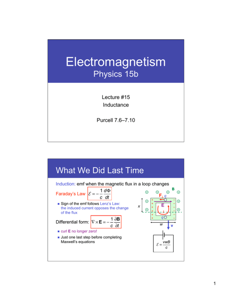
Electromagnetism Physics 15b Lecture #15 Inductance Purcell 7.6–7.10 What We Did Last Time Induction: emf when the magnetic flux in a loop changes B 1 dΦ Faraday’s Law E = − FL q c dt – + Sign of the emf follows Lenz’s Law: the induced current opposes the change of the flux Differential form: ∇ × E = − 1 ∂B c ∂t curl E no longer zero! Just one last step before completing Maxwell’s equations x + + + + + – – – – – E I q w E= v vwB c 1 Today’s Goals Introduce Inductance Mutual inductance – Magnetic interaction between two circuits hanging current in circuit #1 produces an emf in circuit #2 Reciprocity theorem Self inductance – Interaction between a circuit and magnetic field Changing current in circuit produces a “back emf” in itself ... and Inductors Energy stored in inductor L Circuits with L, C and R Mutual Inductance Two wire loops are close to each other Turn on the switch I1 increases B increases emf E2 on the right loop loop 1 loop 2 I1 B E2 dI 1 dΦ 2 Generally true for any pair of circuits ∝− 1 c dt dt Define mutual inductance between loop 1 and loop 2: E2 = − emf in loop 2 Unit: E2 = −M 21 dI1 dt current in loop 1 M 21 ≡ 1 Φ2 c I1 flux in loop 2 [emf] esu cm sec 2 in CGS = = [current]/[time] esu sec 2 cm 2 Big Loop and Small Loop Two concentric loops C1 and C2, with radii R1 >> R2 Current I1 on C1 produces B inside C2 From Lecture 12 B= 2π I1 cR1 B C1 C2 Biot-Savart If R2 is really small I1 2π 2I1R22 Φ 2 = ∫ B ⋅ da 2 ≈ B ⋅ π R = C2 cR1 2 2 2π R M 21 = 2 2 c R1 2 2 The “reverse” inductance M12 is much harder to calculate in this case — but we don’t have to… Reciprocity Theorem For any two circuits C1 and C2, related by dI dI E2 = −M 21 1 and E1 = −M12 2 M12 dt dt Proof: we can express M12 as Φ 1 M 21 = 2 = B ⋅ da 2 cI1 cI1 ∫S2 1 cI1 ∫ S2 (∇ × A) ⋅ da 2 = C2 C1 I1 Use B = ∇×A and apply Stokes M 21 = = M 21 1 ∫C2 A ⋅ d s2 cI1 da2 ds1 r12 ds2 Express A using integral of I1 over C1 (Biot-Savart) M 21 = I1ds1 1 1 ⋅ d s2 = 2 ∫ ∫ cI1 C2 C1 cr12 c ds1 ⋅ ds 2 C1 r12 ∫ ∫ C2 This is symmetric between 1 and 2 3 Self Inductance We don’t really need two circuits to find inductance Any circuit produces B field B field changes when the current I changes emf appears on the circuit itself I B Define self inductance L as E = −L dI dt or L≡ 1Φ c I Minus sign comes from Lenz’s law whenever the current changes, the circuit tends to resist the change E is also known as the “back emf” Inductor (a.k.a. Coil) Wire wound in a coil has a large self inductance Core can be empty (air-core) Ferromagnetic (e.g. iron) core enhances the inductance E = −L emf against I B B inside a long air-core coil is 4π NI B= c dI dt I increases Caution: the coil wraps around the same B field N times Φ = NBA = 4π N 2IA c Φ 4π N 2 A L= = cI c 2 Having many turns help 4 Energy in Inductor Connect an inductor L to a controllable current source Increase current from 0 to I0 over time T I(0) = 0 I(T ) = I0 The current source must flow I against back emf dI V =L dt That’s work, and takes power Total work is T 0 P dt = – + ∫ I ∫ T 0 LI P = IV = LI dI dt V I0 dI 1 dt = L ∫ dI = LI02 0 dt 2 Inductor L flowing current I holds an energy LI 2 U= 2 Energy in Magnetic Field Inductor is nothing but a wire in an empty space Energy is stored in the empty space itself Consider the air-core coil again 4π NI 4π N 2 A We know B = The energy is c U= and L = B c 2 LI 2 4π N 2 AI 2 A 2 1 2 = = B = B × (volume) 2 2 8π 8π 2c Generalize: energy stored in any magnetic field U= 1 8π ∫B 2 dv cf. We saw earlier for E field U = 1 8π ∫E 2 dv 5 Inductors in Circuits What does an inductor do in a circuit? It resists the current change V = φa − φb = L dI dt φa φb I Compare this with R & C V = RI φa φb I V= Q C φa +Q −Q I= φb dQ dt I These rules + Kirchhoff determines current RL Circuit Let’s consider a simple case: R and L with an emf Switch is closed at t = 0 What follows? Step 1: define the direction of I Step 2: apply the loop rule R L I dI E − L − RI = 0 dt Step 3: solve the equation I(t) = + E! − ⎛ R ⎞ E − k exp ⎜ − t ⎟ R ⎝ L ⎠ Step 4: use the initial condition (I(0) = 0) Why is this true? I(t) = ⎛ R ⎞⎞ E⎛ 1− exp ⎜⎝ − L t ⎟⎠ ⎟⎠ R ⎜⎝ 6 RL Circuit An RL circuit is a lot like an RC circuit Current approaches its final value exponentially E R I(t) = R − t⎞ E⎛ L 1− e ⎟ R ⎜⎝ ⎠ L τ =L R E! − t Asymptotic value = what I would be if L were not there Time constant τ= + I R L R LC Circuit An inductor L and a capacitor C are connected in series C has initially a charge Q0 Switch closes at t = 0 Define I and Q dQ Q and I are related: I = + dt +Q I C L -Q Kirchhoff’s loop rule Q dI − −L =0 C dt Q d 2Q +L 2 =0 C dt d 2Q Q =− 2 LC dt This is a differential equation for a simple harmonic oscillator 7 Simple Harmonic Oscillator Mass m is placed on a friction-free floor Spring pulls/pushes the mass m with force F = −kx m Hooke’s Law Newton’s law: d 2x k d 2x =− x 2 2 m dt dt Simple Harmonic Oscillation F=m F −x x(t) = A cos(ω t + φ ) ω= F k is the angular frequency m x LC Circuit An LC circuit is a simple harmonic oscillator Let’s assume the solution is Q(t) = A cos(ω t + φ ) d 2Q Q =− 2 LC dt 2 LHS = −Aω cos(ω t + φ ) A RHS = − cos(ω t + φ ) LC +Q Plug into the differential equation I C L -Q ω= 1 LC Initial conditions (Q(0) = Q0 and I(0) = 0) determine A and φ ⎧⎪ A = Q0 ⎨ ⎪⎩φ = 0 ⎧⎪Q(t) = Q0 cos ω t ⎨ ⎩⎪I(t) = −Q0ω sin ω t 8 Charge and Current Q and I oscillates back and forth Their phases are off by 90 degrees Q0 Q = Q0 cos ω t ωt Q lags behind I −Q0 Period of oscillation Q0ω 2π T= = 2π LC ω I = −Q0ω sin ω t ωt Frequency of oscillation f= 1 1 = T 2π LC −Q0ω Why Oscillate? +Q0 C −Q0 I=0 L C discharges by flowing current thru L 0 I = +Q0ω 0 I = −Q0ω L 0 Charge gone, but L keeps current flowing Charge gone, but L keeps current flowing C 0 C L C discharges by flowing current thru L −Q0 C +Q0 I=0 L 9 Energy Energy is exchanged between C and L Maximum values are: max C U UCmax L(Q0ω )2 U = 2 1 = ULmax for ω = LC Q02 = 2C max L Total energy at any t 2 UC = Q 2 +Q0 C 2C −Q0 UC = 0 C 2 0 Q LI 0 + 2C 2 Q 2 cos2 ω t LQ02ω 2 sin2 ω t = 0 + −Q0 2C 2 Q2 2 U = C Q C 2C +Q = 0 constant 0 2C U= I=0 L UL = 0 I = −Q0w L UL = I=0 L UL = 0 LI 2 2 Energy Energy is exchanged between C and L, but the total remains constant Q2 0 2C The situation is identical to the mass-spring oscillator UC Q02 2C UL m Q02 2C UC UL ωt 10 Summary Inductance Mutual inductance E2 = −M Self inductance E = −L dI dt dI1 dt or E1 = −M L= LI 2 Energy in an inductor U = 2 Energy density in magnetic field Inductors in a circuit: V = L dI dt dI2 Note: reciprocity dt Φ cI emf against I B u= B2 8π RL circuit relaxes exponentially with τ LC circuit oscillates with angular frequency ω = I increases =L R 1 LC 11
