Securitron Magnalock Corp.
Tel 775.355.5625
550 Vista Boulevard
Fax 775.355.5633
Sparks, NV 89434
info@securitron.com
www.securitron.com
ASSA ABLOY, the global leader
in door opening solutions
SECURITRON CONCRETE WOOD HEADER BRACKET
MODELS CWB-32, CWB-62 AND CWB-82
INSTALLATION INSTRUCTIONS
1. PRODUCT DESCRIPTION
The CWB is a 1/2” [12.7mm] thick anodized aluminum concrete wood header bracket with three
(3) individual designs for each of the Models M32, M62 or M82 Magnalocks. Installations that
contain wood door type frames, steel frames and/or steel concrete filled header frames may
require this type of special spacer/structural bracket. The purpose of the CWB concrete wood
header bracket is to improve frame mounting strength, Magnalock/Strike clearances, alignments
and ease of the installation. The brackets are available for all standard mount M32, M62 and
M82 Magnalocks models.
2. PRODUCT OVERVIEW
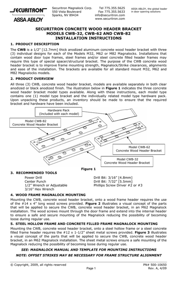
All three (3) CWB, concrete wood header bracket, models are available separately in both clear
anodized or black anodized finish. The illustration below in Figure 1 indicates the three concrete
wood header bracket model types available. Along with these instructions, each model type
contains one (1) model type bracket and the individually related model type hardware pack.
Upon unpacking these products, an inventory should be made to ensure that the required
bracket and hardware have been included.
Hardware Pack
(Included with each model)
Model CWB-82
Concrete Wood Header Bracket
Model CWB-62
Concrete Wood Header Bracket
Model CWB-32
Concrete Wood Header Bracket
Figure 1
3. RECOMMENDED TOOLS
Power Drill
Center Punch
1/2” Wrench or Adjustable
3/16” Hex Wrench
Drill Bit: 3/16” [4.8mm]
Drill Bit: 7/32” [5.5mm]
Phillips Screw Driver #2 or #3
4. WOOD FRAME MAGNALOCK MOUNTING
Mounting the CWB, concrete wood header bracket, onto a wood frame header requires the use
of the #14 x 4” long wood screws provided. Figure 2 illustrates a visual concept of the parts
that will be applied to secure the CWB, concrete wood header bracket, in an M62 Magnalock
installation. The wood screws mount through the door frame and extend into the internal header
to ensure a safe and secure mounting of the Magnalock reducing the possibility of becoming
loose during regular use.
5. STEEL HOLLOW FRAME AND CONCRETE FILLED FRAME MAGNALOCK MOUNTING
Mounting the CWB, concrete wood header bracket, onto a steel hollow frame or a steel concrete
filled frame header requires the #12 x 1-1/2” sheet metal screws provided. Figure 3 illustrates
a visual concept of the parts that will be applied to secure the CWB, concrete wood header
bracket, in an M62 Magnalock installation. The sheet metal screws ensure a safe mounting of the
Magnalock reducing the possibility of becoming loose during regular use.
SEE: MAGNALOCK MANUAL AND TEMPLATE FOR MOUNTING INSTRUCTIONS
NOTE: OFFSET STRIKES MAY BE NECESSARY FOR FRAME STRUCTURE ALIGNMENT
© Copyright, 2009, all rights reserved
Page 1
PN# 500-10650
Rev. A, 4/09
CWB - Concrete Wood Header Bracket
(Included)
#12 x 1-1/2” Screw
(Included)
#14 x 4” Screw
(Included)
Magnalock
(Sold Separately)
1/4” Flat Washers
(Included with Magnalock)
1/4-20 Socket Cap Screws
(Included)
Figure 2
(Wood Type Frames)
Figure 3
(Steel Type Frames)
Wood Type Frames – Step-By-Step Installation Procedures:
•
•
•
•
•
•
•
Position the bracket in the Magnalock mounting location on the frame.
Utilizing the bracket as a template, mark the counter-sink holes where the wood screws will
be located.
Drill the marked locations in the frame using a 7/32” [5.5mm] drill at a minimum depth of
approximately 2-1/2”.
Mount the bracket onto the frame and securely tighten using the #14 x 4” long wood screws
provided.
Drill the hole for the cable access into the frame utilizing the slotted area provided in the
center locations of the concrete wood header bracket.
Position the Magnalock onto the CWB concrete wood header bracket while running the cables
into the cable access area.
Using the 1/4-20 socket head cap screws provided with the bracket hardware and the flat
washers provided with the Magnalock hardware, securely mount the Magnalock into place.
Steel Hollow and Concrete Filled Type Frames – Step-By-Step Installation Procedures:
•
•
•
•
•
•
•
Position the bracket in the Magnalock mounting location on the frame.
Utilizing the bracket as a template, mark the counter-sink holes where sheet metal screws
will be located.
Drill the marked locations in the frame using a 3/16” [4.8mm] drill at a minimum depth of
approximately 1-1/2”.
Mount the bracket onto the frame and securely tighten using the #12 x 1-1/2” sheet metal
screws provided.
Drill the hole for the cable access into the frame utilizing the slotted area provided in the
center locations of the concrete wood header bracket.
Position the Magnalock onto the CWB concrete wood header bracket while running the cables
into the cable access area.
Using the 1/4-20 socket head cap screws provided with the bracket hardware and the flat
washers provided with the Magnalock hardware, securely mount the Magnalock into place.
Page 2
PN# 500-10650
Rev. A, 4/09


