Z-BLOK
BLH
Load Cell Weigh Module
FEATURES
• Capacity range: 500, 1K, 2K, 5K, 10K, 20K, and 50K lb
(227, 454, 907, 2.27K, 4.5K, 9K, and 22.7K kg)
• ‘Checkless’ design - no stay or check rods required
• Low profile and integral thermal expansion assembly
simplifies installation
• Designed to meet ANSI/ASCE wind load and seismic
requirements
• Double cantilever design improves system performance
and accuracy
• FM and CSA approved
DESCRIPTION
APPLICATIONS
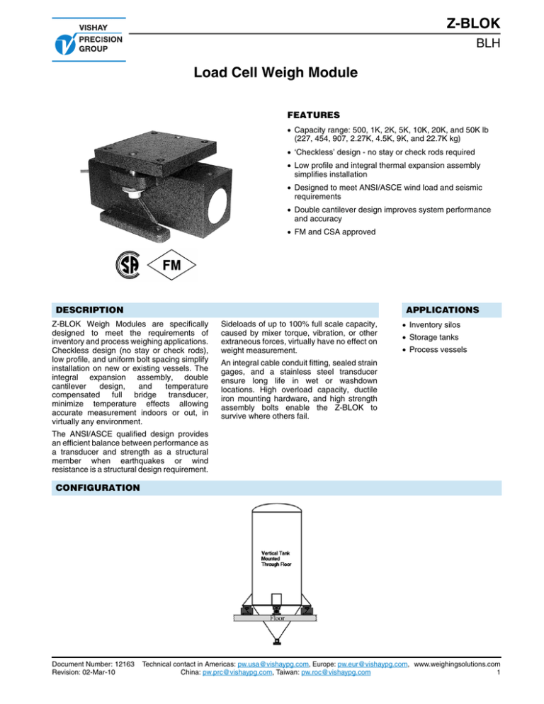
Z-BLOK Weigh Modules are specifically
designed to meet the requirements of
inventory and process weighing applications.
Checkless design (no stay or check rods),
low profile, and uniform bolt spacing simplify
installation on new or existing vessels. The
integral expansion assembly, double
cantilever
design,
and
temperature
compensated
full
bridge transducer,
minimize temperature effects allowing
accurate measurement indoors or out, in
virtually any environment.
Sideloads of up to 100% full scale capacity,
caused by mixer torque, vibration, or other
extraneous forces, virtually have no effect on
weight measurement.
• Inventory silos
• Storage tanks
• Process vessels
An integral cable conduit fitting, sealed strain
gages, and a stainless steel transducer
ensure long life in wet or washdown
locations. High overload capacity, ductile
iron mounting hardware, and high strength
assembly bolts enable the Z-BLOK to
survive where others fail.
The ANSI/ASCE qualified design provides
an efficient balance between performance as
a transducer and strength as a structural
member when earthquakes or wind
resistance is a structural design requirement.
CONFIGURATION
Document Number: 12163
Revision: 02-Mar-10
Technical contact in Americas: pw.usa@vishaypg.com, Europe: pw.eur@vishaypg.com, www.weighingsolutions.com
China: pw.prc@vishaypg.com, Taiwan: pw.roc@vishaypg.com
1
Z-BLOK
BLH
Load Cell Weigh Module
THE DOUBLE CANTILEVER ADVANTAGE
Double cantilever shear beams measure the shear component of force without errors caused by changing point or moment stresses.
The Z-BLOK Weigh Module incorporates an outer sleeve
that can be thought of as a second cantilever, rigidly attached
to the free end of the first cantilever. Thus the term double
cantilever.
With this design, rather than applying force at the free end of
the beam, the point of load application is brought back to a
point directly over the gaged area. The result is that bending
moment is close to zero across the gaged area. Because a
shear beam is designed to measure shear, not bending, any
reduction in bending moment stress is desirable. The second
cantilever also is effective at isolating load application point
stresses from the active element.
Reducing the force due to bending moment in a cantilever
beam has a side benefit - a reduction in the beam’s strength
requirements. By reducing the bending moment induced at
the weakest part of the shear beam (section A-A), a double
cantilever shear beam can be operated at a stress level well
below that of a single cantilever shear beam. The result is a
more conservative structural design with high overload capacity and fatigue resistance.
Double cantilever shear beams approach the ideal in load
cell design; they measure the desired force while ignoring
any extraneous forces that may be present.
THE INTEGRAL THERMAL EXPANSION/RETAINER PLATE ADVANTAGE
Z-BLOK’s unique design incorporates an integral expansion/retainer plate assembly with retainer bolts. This mounting arrangement provides simple checkless installation while
allowing for minor mounting surface irregularities and vessel/structure expansion and contraction. The spherical load
button and socket eliminates torsional stresses on the load
element caused by non-level or out of plumb mounting
surfaces.
End load stresses, caused by vessel/structure expansion
and contraction or process vibration, are negated by the
teflon impregnated slide plate. The expansion/retainer plate
assembly is attached to the module at the factory and requires no adjustments. The high strength bolts that connect
the module and expansion/retainer plate assembly provide
resistance to uplift forces and complete the checkless design.
www.weighingsolutions.com Technical contact in Americas: pw.usa@vishaypg.com, Europe: pw.eur@vishaypg.com,
2
China: pw.prc@vishaypg.com, Taiwan: pw.roc@vishaypg.com
Document Number: 12163
Revision: 02-Mar-10
Z-BLOK
Load Cell Weigh Module
BLH
OUTLINE DIMENSIONS
Dimensions shown in mm (in.)
Document Number: 12163
Revision: 02-Mar-10
Technical contact in Americas: pw.usa@vishaypg.com, Europe: pw.eur@vishaypg.com, www.weighingsolutions.com
China: pw.prc@vishaypg.com, Taiwan: pw.roc@vishaypg.com
3
Z-BLOK
BLH
Load Cell Weigh Module
SPECIFICATIONS
Performance
Capacities
500, 1K, 2K, 5K, 10K, 20K,
and 50K lb,
(227, 454, 907, 2.27K, 4.5K, 9K,
and 22.7K kg)
Rated Output (RO)
2.0 mV/V +/-0.1% mV/V
Repeatability
0.01 % RO
Combined Error (best fit) 0.10% RO
Zero Balance
5% RO
Creep (20 minutes)
0.03% RO
Temperature Effects:
On Zero Balance
0.0017% RO/°F
On Span
0.0020%Load/ °F
Electrical
Recommended Excitation 10 Vdc (15 Vdc max)
Input Resistance
350 ohms + /- 3 ohms
Output Resistance
350 ohms + /- 3 ohms
Cable Length
32’, 10 cable with
conduit fitting
Temperature
Safe Range
-40 to 220°F
Compensated Range
+30 to 130°F
Adverse Load Ratings
Safe Load
150% rated capacity
Safe Sideload
100% rated capacity
Safe Uplift
50% rated capacity
Material
Beam
15-5PH Stainless Steel
Brackets
painted* ductile iron
Deflection and Unit Weight
CAPACITY
DEFLECTION WEIGHT
500 lb
0.012 in.
10 lb
1K lb
0.012 in.
10 lb
2K lb
0.013 in.
15 lb
5K lb
0.027 in.
15 lb
10K lb
0.023 in.
35 lb
20K 1b
0.047 in.
50 lb
50K lb
0.066 in.
75 lb
Approvals
FM Intrinsically Safe
Class I, II, III; Div 1, Groups A-G
FM Nonincendive
Class I; Div 2, Groups A-D
CSA Intrinsically Safe
Class I, Groups A-D; Class II,
Groups E-G
*single component, waterborne polyurethane copolymer - high gloss
BLH is continually seeking to improve product quality and performance. Specifications may change accordingly.
SIMULATED WEIGH MODULES
Thermal Insulation Pads
In applications where heat conduction is a concern, BLH can provide thermal pads to isolate the Z-BLOK modules from the hot
vessel. The one inch thick, phenolic glass pads install directly between the Z-BLOK expansion/retainer plate and the vessel
gusset/mounting bracket for thermal insulation.
www.weighingsolutions.com Technical contact in Americas: pw.usa@vishaypg.com, Europe: pw.eur@vishaypg.com,
4
China: pw.prc@vishaypg.com, Taiwan: pw.roc@vishaypg.com
Document Number: 12163
Revision: 02-Mar-10
Legal Disclaimer Notice
Vishay Precision Group, Inc.
Disclaimer
ALL PRODUCTS, PRODUCT SPECIFICATIONS AND DATA ARE SUBJECT TO CHANGE WITHOUT NOTICE.
Vishay Precision Group, Inc., its affiliates, agents, and employees, and all persons acting on its or their behalf
(collectively, “VPG”), disclaim any and all liability for any errors, inaccuracies or incompleteness contained herein or in
any other disclosure relating to any product.
The product specifications do not expand or otherwise modify VPG’s terms and conditions of purchase, including but
not limited to, the warranty expressed therein.
VPG makes no warranty, representation or guarantee other than as set forth in the terms and conditions of purchase.
To the maximum extent permitted by applicable law, VPG disclaims (i) any and all liability arising out of the
application or use of any product, (ii) any and all liability, including without limitation special, consequential or
incidental damages, and (iii) any and all implied warranties, including warranties of fitness for particular purpose,
non-infringement and merchantability.
Information provided in datasheets and/or specifications may vary from actual results in different applications and
performance may vary over time. Statements regarding the suitability of products for certain types of applications
are based on VPG’s knowledge of typical requirements that are often placed on VPG products. It is the customer’s
responsibility to validate that a particular product with the properties described in the product specification is suitable for
use in a particular application. You should ensure you have the current version of the relevant information by contacting
VPG prior to performing installation or use of the product, such as on our website at vpgsensors.com.
No license, express, implied, or otherwise, to any intellectual property rights is granted by this document, or by any
conduct of VPG.
The products shown herein are not designed for use in life-saving or life-sustaining applications unless otherwise
expressly indicated. Customers using or selling VPG products not expressly indicated for use in such applications do
so entirely at their own risk and agree to fully indemnify VPG for any damages arising or resulting from such use or sale.
Please contact authorized VPG personnel to obtain written terms and conditions regarding products designed for such
applications.
Product names and markings noted herein may be trademarks of their respective owners.
Copyright Vishay Precision Group, Inc., 2014. All rights reserved.
Document No.: 63999
Revision: 15-Jul-2014
www.vpgsensors.com
1


