TDD-D-1
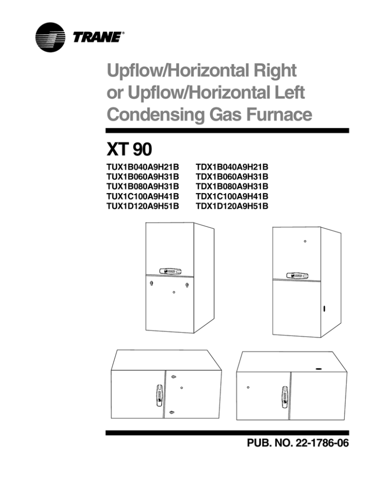
Upflow/Horizontal Right
or Upflow/Horizontal Left
Condensing Gas Furnace
XT 90
TUX1B040A9H21B
TUX1B060A9H31B
TUX1B080A9H31B
TUX1C100A9H41B
TUX1D120A9H51B
TDX1B040A9H21B
TDX1B060A9H31B
TDX1B080A9H31B
TDX1C100A9H41B
TDX1D120A9H51B
PUB. NO. 22-1786-06
General
Features
NATURAL GAS MODELS
Central Heating furnace designs are
certified by the American and Canadian
Gas Association for both natural and L.P.
gas. Limit setting and rating data were
established and approved under standard rating conditions using American
National Standards Institute standards.
SAFE OPERATION
The Integrated System Control has solid
state devices, which continuously monitor
for presence of flame, when the system is
in the heating mode of operation. Dual
solenoid combination gas valve and
regulator provide extra safety.
QUICK HEATING
Durable, cycle tested, heavy gauge
aluminized steel heat exchanger
quickly transfers heat to provide warm
conditioned air to the structure. Low
energy power vent blower, to increase
efficiency and provide a positive discharge of gas fumes to the outside.
BURNERS
Multiport Inshot burners will give years of
quiet and efficient service. All models
can be converted to L.P. gas without
changing burners.
INTEGRATED SYSTEM CONTROL
Exclusively designed operational program provides total control of furnace
limit sensors, blowers, gas valve, flame
control and includes self diagnostics for
ease of service. Also contains connection points for E.A.C./humidifier.
© 2009 Trane
All Rights Reserved
2
AIR DELIVERY
The four speed, direct drive blower
motor, has sufficient airflow for most
heating and cooling requirements, will
switch from heating to cooling speeds on
demand from room thermostat. The
blower door safety switch will prevent or
terminate furnace operation when the
blower door is removed.
STYLING
Heavy gauge steel and “wrap-around”
cabinet construction is used in the
cabinet with baked-on enamel finish for
strength and beauty. The heat exchanger section of the cabinet is completely lined with foil faced fiberglass
insulation. This results in quiet and
efficient operation due to the excellent
acoustical and insulating qualities of
fiberglass. Built-in bottom pan and
alternate bottom, left or right side return
air connection provision.
FEATURES AND
GENERAL OPERATION
The XT90 High Efficiency Gas Furnaces
employ a Silicon Carbide Hot Surface
Ignition system, which eliminates the
waste of a constant burning pilot. The
integrated system control lights the main
burners upon a demand for heat from the
room thermostat. Complete front service
access.
a. Low energy power venter
b. Vent proving pressure switch.
Pub. No. 22-1786-06
Contents
General Features
2
Features and Benefits
4
Standard Equipment
Optional Equipment
General Data
Pub. No. 22-1786-06
4
4
5
TUX1B040A9H21B
TUX1B060A9H31B
TUX1B080A9H31B
TUX1C100A9H41B
TUX1D120A9H51B
TDX1B040A9H21B
TDX1B060A9H31B
TDX1B080A9H31B
TDX1C100A9H41B
TDX1D120A9H51B
5
5
6
6
6
7
7
7
7
8
Performance Data
10
Field Wiring
12
Dimensions
14
Electrical Data
15
3
Features
and Benefits
XT 90 UPFLOW/HORIZONTAL RIGHT or LEFT STANDARD EQUIPMENT
• Convertible to horizontal with left or
right airflow
• Gasketed blower door
• Common vent capability
• Internal filter rack
• Power supply 115/1/60
• Type 29-4CTM stainless steel
secondary heat exchanger
• Standard filter sizes
• Heavy gauge reinforced wrap-around
steel cabinet
• Cleanable high velocity filters
• Optional L.P. conversion kit
• Silicon Nitride Hot surface igniter with
adaptive heat up
• Heavy gauge aluminized steel heat
exchanger
• Left/right gas connection
• Integrated solid state control with selfdiagnostics
• Blower door safety switch
• Multi-port In-shot burners
• Selectable cooling fan off eliminates
need for BAY24X045 time delay relay
• Single wire twinning
• Complete front service access
• 24 volt fuse
• Attractive color accents
• Alternate bottom/left/right return air
• Manual reset flame roll-out switches
• Hinged blower door
• Slide out blower assembly
• Prefect Fit door latches
• Constant torque ECM blower motor
• Insulated blower door
• Adjustable fan off times
• Accessory hook-up capability
XT90 Optional Equipment
✓ ] indicates accessories included).
OPTIONAL EQUIPMENT FOR CONDENSING UNITS (Check mark [✓
For Comfort Controls, See price book pages ................................................................................................................................ [
CleanEffectsTM Whole House Air Cleaner (14-1/2" Wide, Upflow / Side Return Furnace) ............................... TFD145ALFR000A [
CleanEffectsTM Whole House Air Cleaner (17-1/2" Wide, Upflow / Side Return Furnace) ............................... TFD175ALFR000A [
CleanEffectsTM Whole House Air Cleaner (21" Wide, Upflow / Side Return Furnace) ..................................... TFD210ALFR000A [
CleanEffectsTM Whole House Air Cleaner (24-1/2" Wide, Upflow / Side Return Furnace) ............................... TFD245ALFR000A [
CleanEffectsTM Whole House Air Cleaner (14-1/2" Wide, Downflow Furnace) ............................................... TFD14DALFR000A [
CleanEffectsTM Whole House Air Cleaner (17-1/2" Wide, Downflow Furnace) ............................................... TFD17DALFR000A [
CleanEffectsTM Whole House Air Cleaner (21" Wide, Downflow Furnace) ..................................................... TFD21DALFR000A [
CleanEffectsTM Whole House Air Cleaner (24-1/2" Wide, Downflow Furnace) ............................................... TFD24DALFR000A [
Air Filter, “Perfect Fit” High Efficiency (14-1/2" Wide Gas Furnace) ....................................................................... TFM145A9FR0 [
Air Filter, “Perfect Fit” High Efficiency (17-1/2" Wide Gas Furnace) ....................................................................... TFM175A9FR0 [
Air Filter, “Perfect Fit” High Efficiency (21" Wide Gas Furnace) ............................................................................. TFM210A9FR0 [
Air Filter, “Perfect Fit” High Efficiency (24-1/2" Wide Gas Furnace) ....................................................................... TFM245A9FR0 [
Air Filter, “Perfect Fit” Standard Efficiency (14-1/2" Wide Gas Furnace) ................................................................ TFP145A9FR0 [
Air Filter, “Perfect Fit” Standard Efficiency (17-1/2" Wide Gas Furnace) ................................................................ TFP175A9FR0 [
Air Filter, “Perfect Fit” Standard Efficiency (21" Wide Gas Furnace) ...................................................................... TFP210A9FR0 [
Air Filter, “Perfect Fit” Standard Efficiency (24-1/2" Wide Gas Furnace) ................................................................ TFP245A9FR0 [
Coil Enclosure (14-1/2" Wide Cabinets) .......................................................................................................... BAYCLE14A1422A [
Coil Enclosure (17-1/2" Wide Cabinets) .......................................................................................................... BAYCLE17A1722A [
Coil Enclosure (21" Wide Cabinets) ................................................................................................................ BAYCLE21A2130A [
Coil Enclosure (24-1/2" Wide Cabinets) .......................................................................................................... BAYCLE24A2430A [
High Altitude Switch ................................................................................................................................................ BAYHALT248 [
Downflow Subbase ................................................................................................................................................. BAYBASE205 [
Propane Conversion Kit ........................................................................................................................................ BAYLPKT210B [
Propane Conversion Kit (With Stainless Steel burners) ......................................................................................... BAYLPSS210B [
Masonry Chimney Vent Kit .................................................................................................................................. BAYVENT800B [
Filter Access Door Kit (Downflow models) ............................................................................................................... BAYFLTR206 [
4
]
]
]
]
]
]
]
]
]
]
]
]
]
]
]
]
]
]
]
]
]
]
]
]
]
]
]
Pub. No. 22-1786-06
General
Data
PRODUCT SPECIFICATIONS 1
MODEL
TYPE
RATINGS 2
Input BTUH
Capacity BTUH (ICS) 3
AFUE
Temp. rise (Min.-Max.) °F.
BLOWER DRIVE
Diameter - Width (In.)
No. Used
Speeds (No.)
CFM vs. in. w.g.
Motor HP 5
R.P.M.
Volts / Ph / Hz
COMBUSTION FAN - Type
Drive - No. Speeds
Motor HP - RPM
Volts / Ph / Hz
FLA
FILTER — Furnished?
Type Recommended
Hi Vel. (No.-Size-Thk.)
VENT PIPE DIAMETER— Min (in.)67
HEAT EXCHANGER
Type-Fired
-Unfired
Gauge (Fired)
ORIFICES — Main
Nat. Gas. Qty. — Drill Size
L.P. Gas Qty. — Drill Size
GAS VALVE
PILOT SAFETY DEVICE
Type
BURNERS — Type
Number
POWER CONN. — V / Ph / Hz 4
Ampacity (In Amps)
Max Overcurrent Protection (Amps)
PIPE CONN. SIZE (IN.)
DIMENSIONS
Crated (In.)
WEIGHT
Shipping (Lbs.) / Net (Lbs)
TUX1B040A9H21B
Upflow / Horizontal
TUX1B060A9H31B
Upflow / Horizontal
TUX1B080A9H31B
Upflow / Horizontal
40,000
38,000
92.1
30 - 60
DIRECT
10 x 7
1
4
60,000
56,000
92.1
30 - 60
DIRECT
10 x 7
1
4
80,000
74,000
92.1
35 - 65
DIRECT
10 x 8
1
4
See Fan Performance Table
See Fan Performance Table
See Fan Performance Table
1/2
1075
115/1/60
Centrifugal
Direct - 1
1/55 - 3000
115/1/60
1.0
Yes
High Velocity
1 - 17x25 - 1in.
2 Round
1/2
1075
115/1/60
Centrifugal
Direct - 1
1/55- 3000
115/1/60
1.0
Yes
High Velocity
1 - 17x25 - 1in.
2 Round
1/2
1075
115/1/60
Centrifugal
Direct - 1
1/24 - 3200
115/1/60
1.35
Yes
High Velocity
1 - 17x25 - 1in.
2 Round
Aluminized Steel
Aluminized Steel
Aluminized Steel
20
20
20
2 — 45
2 — 56
3 — 45
3 — 56
4 — 45
4 — 56
Redundant - Single Stage
Redundant - Single Stage
Redundant - Single Stage
Hot Surface Ignition
Multiport Inshot
2
115/1/60
9.7
15
1/2
HxWxD
Hot Surface Ignition
Multiport Inshot
3
115/1/60
9.7
15
1/2
HxWxD
Hot Surface Ignition
Multiport Inshot
4
115/1/60
10.0
15
1/2
HxWxD
41-3/4 x 19-1/2 x 30-1/2
41-3/4 x 19-1/2 x 30-1/2
41-3/4 x 19-1/2 x 30-1/2
139 / 129
150 / 140
158 / 148
1 Central Furnace heating designs are certified by AGA and CSA.
2 For U.S. applications, above input ratings (BTUH) are up to 2,000 feet, derate 4% per 1,000 feet for elevations above 2,000 feet above sea level.
For Canadian applicaitons, above input ratings (BTUH) are up to 4,500 feet, derate 4% per 1,000 feet for elevations above 4,500 feet above sea level.
3 Based on U.S. government standard tests.
4 The above wiring specifications are in accordance with National Electrical Code; however, installations must comply with local codes.
5 Constant torque ECM blower motor.
6 Refer to the Vent Length Table in the Installer's Guide or the Allowable Vent Length labelon the furnace.
7 All *UX1 and *DX1 furnace models have a vent outlet diameter that equals 2".
Pub. No. 22-1786-06
5
General
Data
PRODUCT SPECIFICATIONS 1
MODEL
TYPE
RATINGS 2
Input BTUH
Capacity BTUH (ICS) 3
AFUE
Temp. rise (Min.-Max.) °F.
BLOWER DRIVE
Diameter - Width (In.)
No. Used
Speeds (No.)
CFM vs. in. w.g.
Motor HP 5
R.P.M.
Volts / Ph / Hz
COMBUSTION FAN - Type
Drive - No. Speeds
Motor HP - RPM
Volts / Ph / Hz
FLA
FILTER — Furnished?
Type Recommended
Hi Vel. (No.-Size-Thk.)
VENT PIPE DIAMETER— Min (in.)67
HEAT EXCHANGER
Type-Fired
-Unfired
Gauge (Fired)
ORIFICES — Main
Nat. Gas. Qty. — Drill Size
L.P. Gas Qty. — Drill Size
GAS VALVE
PILOT SAFETY DEVICE
Type
BURNERS — Type
Number
POWER CONN. — V / Ph / Hz 4
Ampacity (In Amps)
Max Overcurrent Protection (Amps)
PIPE CONN. SIZE (IN.)
DIMENSIONS
Crated (In.)
WEIGHT
Shipping (Lbs.) / Net (Lbs)
TUX1C100A9H41B
Upflow / Horizontal
TUX1D120A9H51B
Upflow / Horizontal
100,000
93,000
92.1
35 - 65
DIRECT
11 x 10
1
4
120,000
112,000
92.1
40 - 70
DIRECT
11 x 10
1
4
See Fan Performance Table
See Fan Performance Table
3/4
1100
115/1/60
Centrifugal
Direct - 1
1/20- 3450
115/1/60
.71
Yes
High Velocity
1 - 20x25 - 1in.
2.5 Round
1
1100
115/1/60
Centrifugal
Direct - 1
1/20- 3450
115/1/60
.71
Yes
High Velocity
1 - 24x25 - 1in.
2.5 Round
Aluminized Steel
Aluminized Steel
20
20
5 — 45
5 — 56
6 — 45
6 — 56
Redundant - Single Stage
Redundant - Single Stage
Hot Surface Ignition
Multiport Inshot
5
115/1/60
12.4
20
1/2
HxWxD
Hot Surface Ignition
Multiport Inshot
6
115/1/60
14.5
20
1/2
HxWxD
41-3/4 x 23 x 30-1/2
41-3/4 x 26-1/2 x 30-1/2
171 / 162
205 / 193
1 Central Furnace heating designs are certified by AGA and CSA.
2 For U.S. applications, above input ratings (BTUH) are up to 2,000 feet, derate 4% per 1,000 feet for elevations above 2,000 feet above sea level.
For Canadian applicaitons, above input ratings (BTUH) are up to 4,500 feet, derate 4% per 1,000 feet for elevations above 4,500 feet above sea level.
3 Based on U.S. government standard tests.
4 The above wiring specifications are in accordance with National Electrical Code; however, installations must comply with local codes.
5 Constant torque ECM blower motor.
6 Refer to the Vent Length Table in the Installer's Guide or the Allowable Vent Length labelon the furnace.
7 All *UX1 and *DX1 furnace models have a vent outlet diameter that equals 2".
6
Pub. No. 22-1786-06
General
Data
PRODUCT SPECIFICATIONS 1
MODEL
TYPE
RATINGS 2
Input BTUH
Capacity BTUH (ICS) 3
AFUE
Temp. rise (Min.-Max.) °F.
BLOWER DRIVE
Diameter - Width (In.)
No. Used
Speeds (No.)
CFM vs. in. w.g.
Motor HP 5
R.P.M.
Volts / Ph / Hz
COMBUSTION FAN - Type
Drive - No. Speeds
Motor HP - RPM
Volts / Ph / Hz
FLA
FILTER — Furnished?
Type Recommended
Hi Vel. (No.-Size-Thk.)
VENT PIPE DIAMETER— Min (in.)67
HEAT EXCHANGER
Type-Fired
-Unfired
Gauge (Fired)
ORIFICES — Main
Nat. Gas. Qty. — Drill Size
L.P. Gas Qty. — Drill Size
GAS VALVE
PILOT SAFETY DEVICE
Type
BURNERS — Type
Number
POWER CONN. — V / Ph / Hz 4
Ampacity (In Amps)
Max Overcurrent Protection (Amps)
PIPE CONN. SIZE (IN.)
DIMENSIONS
Crated (In.)
WEIGHT
Shipping (Lbs.) / Net (Lbs)
TDX1B040A9H21B
Downflow / Horizontal
TDX1B060A9H31B
Downflow / Horizontal
TDX1B080A9H31B
Downflow / Horizontal
40,000
38,000
91.0
30 - 60
DIRECT
10 x 7
1
4
60,000
56,000
91.0
30 - 60
DIRECT
10 x 8
1
4
80,000
74,000
91.0
35 - 65
DIRECT
10 x8
1
4
See Fan Performance Table
See Fan Performance Table
See Fan Performance Table
1/2
1080
115/1/60
Centrifugal
Direct - 1
1/55- 3000
115/1/60
1.14
Yes
High Velocity
1 - 14x20 - 1in.
2 Round
1/2
1075
115/1/60
Centrifugal
Direct - 1
1/55- 3000
115/1/60
1.0
Yes
High Velocity
2 - 14x20 - 1in.
2 Round
3/4
1075
115/1/60
Centrifugal
Direct - 1
1/25- 3200
115/1/60
1.35
Yes
High Velocity
2 - 14x20 - 1in.
2 Round
Aluminized Steel
Aluminized Steel
Aluminized Steel
20
20
20
2 — 45
2 — 56
3 — 45
3 — 56
4 — 45
4 — 56
Redundant - Single Stage
Redundant - Single Stage
Redundant - Single Stage
Hot Surface Ignition
Multiport Inshot
2
115/1/60
9.7
15
1/2
HxWxD
Hot Surface Ignition
Multiport Inshot
3
115/1/60
9.7
15
1/2
HxWxD
Hot Surface Ignition
Multiport Inshot
4
115/1/60
12.4
15
1/2
HxWxD
41-3/4 x 19-1/2 x 30-1/2
41-3/4 x 19-1/2 x 30-1/2
41-3/4 x 19-1/2 x 30-1/2
145 / 135
155 / 145
168 / 158
1 Central Furnace heating designs are certified by AGA and CSA.
2 For U.S. applications, above input ratings (BTUH) are up to 2,000 feet, derate 4% per 1,000 feet for elevations above 2,000 feet above sea level.
For Canadian applicaitons, above input ratings (BTUH) are up to 4,500 feet, derate 4% per 1,000 feet for elevations above 4,500 feet above sea level.
3 Based on U.S. government standard tests.
4 The above wiring specifications are in accordance with National Electrical Code; however, installations must comply with local codes.
5 Constant torque ECM blower motor.
6 Refer to the Vent Length Table in the Installer's Guide or the Allowable Vent Length labelon the furnace.
7 All *UX1 and *DX1 furnace models have a vent outlet diameter that equals 2".
Pub. No. 22-1786-06
7
General
Data
PRODUCT SPECIFICATIONS 1
MODEL
TYPE
RATINGS 2
Input BTUH
Capacity BTUH (ICS) 3
AFUE
Temp. rise (Min.-Max.) °F.
BLOWER DRIVE
Diameter - Width (In.)
No. Used
Speeds (No.)
CFM vs. in. w.g.
Motor HP 5
R.P.M.
Volts / Ph / Hz
COMBUSTION FAN - Type
Drive - No. Speeds
Motor HP - RPM
Volts / Ph / Hz
FLA
FILTER — Furnished?
Type Recommended
Hi Vel. (No.-Size-Thk.)
VENT PIPE DIAMETER— Min (in.)67
HEAT EXCHANGER
Type-Fired
-Unfired
Gauge (Fired)
ORIFICES — Main
Nat. Gas. Qty. — Drill Size
L.P. Gas Qty. — Drill Size
GAS VALVE
PILOT SAFETY DEVICE
Type
BURNERS — Type
Number
POWER CONN. — V / Ph / Hz 4
Ampacity (In Amps)
Max Overcurrent Protection (Amps)
PIPE CONN. SIZE (IN.)
DIMENSIONS
Crated (In.)
WEIGHT
Shipping (Lbs.) / Net (Lbs)
TDX1C100A9H41B
Downflow / Horizontal
TDX1D120A9H51B
Downflow / Horizontal
100,000
94,000
91.0
35 - 65
DIRECT
11 x 10
1
4
120,000
110,000
91.0
40 - 70
DIRECT
11 x 10
1
4
See Fan Performance Table
See Fan Performance Table
3/4
1075
115/1/60
Centrifugal
Direct - 1
1/20- 3450
115/1/60
.71
Yes
High Velocity
2 - 16x20 - 1in.
2.5 Round
1
1075
115/1/60
Centrifugal
Direct - 1
1/20- 3450
115/1/60
.71
Yes
High Velocity
2 - 16x20 - 1in.
2.5 Round
Aluminized Steel
Aluminized Steel
20
20
5 — 45
5 — 56
6 — 45
6 — 56
Redundant - Single Stage
Redundant - Single Stage
Hot Surface Ignition
Multiport Inshot
5
115/1/60
12.4
20
1/2
HxWxD
Hot Surface Ignition
Multiport Inshot
6
115/1/60
15.5
20
1/2
HxWxD
41-3/4 x 23 x 30-1/2
41-3/4 x 26-1/2 x 30-1/2
185 / 175
206 / 196
1 Central Furnace heating designs are certified by AGA and CSA.
2 For U.S. applications, above input ratings (BTUH) are up to 2,000 feet, derate 4% per 1,000 feet for elevations above 2,000 feet above sea level.
For Canadian applicaitons, above input ratings (BTUH) are up to 4,500 feet, derate 4% per 1,000 feet for elevations above 4,500 feet above sea level.
3 Based on U.S. government standard tests.
4 The above wiring specifications are in accordance with National Electrical Code; however, installations must comply with local codes.
5 Constant torque ECM blower motor.
6 Refer to the Vent Length Table in the Installer's Guide or the Allowable Vent Length labelon the furnace.
7 All *UX1 and *DX1 furnace models have a vent outlet diameter that equals 2".
8
Pub. No. 22-1786-06
Performance
Data
FURNACE AIRFLOW (CFM) VS. STATIC PRESSURE (ins.w.g.)
MODEL
SPEED TAP
0.1
0.2
0.3
0.4
0.5
0.6
0.7
0.8
0.9
*UX1B040A9H21B
4 - HIGH - Black
3 - MED-HIGH - Blue
2 - MED-LOW - Yellow
1 - LOW - Red
1159
938
844
772
1131
910
814
732
1102
881
783
691
1077
851
750
656
1052
820
717
621
1022
786
681
581
992
751
645
540
961
717
604
497
930
662
563
454
*UX1B060A9H31B
4 - HIGH - Black
3 - MED-HIGH - Blue
2 - MED-LOW - Yellow
1 - LOW - Red
1358
1196
1025
863
1327
1166
1000
830
1296
1135
975
797
12721109
943
762
1248
1082
910
726
1215
1053
878
687
1182
1023
845
648
1122
989
813
601
1061
955
780
554
*UX1B080A9H31B
4 - HIGH - Black
3 - MED-HIGH - Blue
2 - MED-LOW - Yellow
1 - LOW - Red
1436
1334
1239
1160
1404
1308
1209
1131
1371
1281
1179
1101
1346
1250
1149
1070
1320
1219
1119
1039
1289
1193
1090
1007
1257
1167
1060
974
1214
1132
1030
940
1170
1097
999
905
*UX1C100A9H41B
4 - HIGH - Black
3 - MED-HIGH - Blue
2 - MED-LOW - Yellow
1 - LOW - Red
1888
1751
1530
1245
1852
1715
1491
1204
1815
1679
1452
1162
1776
1643
1415
1115
1737
1606
1378
1067
1698
1571
1336
1023
1659
1536
1293
979
1626
1493
1253
931
1593
1450
1212
882
*UX1D120A9H51B
4 - HIGH - Black
3 - MED-HIGH - Blue
2 - MED-LOW - Yellow
1 - LOW - Red
2153
1895
1777
1618
2121
1856
1743
1579
2089
1817
1708
1540
2056
1779
1673
1504
2023
1741
1637
1467
1983
1708
1601
1430
1943
1674
1564
1393
1907
1634
1524
1354
1870
1593
1484
1315
*DX1B040A9H21B
4 - HIGH - Black
3 - MED-HIGH - Blue
2 - MED-LOW - Yellow
1 - LOW - Red
1156
935
835
752
1128
859
803
726
1100
859
771
700
1072
828
736
648
1043
797
701
596
1012
757
652
554
981
717
602
511
917
679
569
471
852
641
536
431
*DX1B060A9H31B
4 - HIGH - Black
3 - MED-HIGH - Blue
2 - MED-LOW - Yellow
1 - LOW - Red
1337
1159
967
863
1314
1127
930
823
1291
1094
893
782
1257
1065
856
742
1223
1036
818
702
1187
997
774
657
1150
957
729
611
1090
920
690
571
1030
883
651
531
*DX1B080A9H31B
4 - HIGH - Black
3 - MED-HIGH - Blue
2 - MED-LOW - Yellow
1 - LOW - Red
1614
1322
1098
970
1585
1295
1067
934
1555
1267
1036
898
1489
1239
1003
868
1423
1211
970
837
1363
1180
933
794
1303
1149
896
750
1202
1111
864
712
1101
1072
831
674
*DX1C100A9H41B
4 - HIGH - Black
3 - MED-HIGH - Blue
2 - MED-LOW - Yellow
1 - LOW - Red
1844
1748
1429
1203
1808
1716
1392
1134
1771
1683
1354
1124
1736
1648
1312
1077
1700
1612
1269
1029
1669
1574
1235
983
1638
1535
1200
937
1590
1497
1154
887
1542
1459
1108
837
4 - HIGH - Black
3 - MED-HIGH - Blue
2 - MED-LOW - Yellow
1 - LOW - Red
2162
1928
1782
1552
2127
1888
1743
1520
2091
1848
1703
1488
2049
1811
1665
1450
2006
1774
1626
1412
1964
1736
1582
1370
1922
1698
1537
1328
1849
1653
1500
1295
1775
1607
1462
1261
NOTE: Do NOT use the
LOW speed tap for heating
*DX1D120A9H51B
* May be "A" or "T"
Pub. No. 22-1786-06
9
Performance
Data
CFM VS. TEMPERATURE RISE
CFM (CUBIC FEET PER MINUTE)
MODEL
400 500 600 700 800 900 1000
*UX1B040A9H21B
56
48
*UX1B060A9H31B
1100
1200
1300
1400
1500
1600
1700
1800
1900
2000
2100
42
37
33
30
63
56
50
45
42
38
36
33
31
29
67
61
56
51
48
44
42
39
37
35
64
60
56
52
49
46
44
42
40
71
67
63
59
56
53
50
48
1800
1900
2000
2100
*UX1B080A9H31B
*UX1C100A9H41B
*UX1D120A9H51B
* May be "A" or "T"
CFM VS. TEMPERATURE RISE
MODEL
CFM (CUBIC FEET PER MINUTE)
400 500 600 700 800 900 1000
*DX1B040A9H21B
*DX1B060A9H31B
*DX1B080A9H31B
56
48
1100
1200
1300
1400
1500
1600
1700
42
37
33
30
63
56
50
45
42
38
36
33
31
29
67
61
56
51
48
44
42
39
37
35
64
60
56
52
49
46
44
42
40
71
67
63
59
56
53
50
48
*DX1C100A9H41B
*DX1D120A9H51B
* May be "A" or "T"
10
Pub. No. 22-1786-06
Field
Wiring
FIELD WIRING DIAGRAM FOR 1 STAGE FURNACE
1 STAGE HEATING
USING A 1 STAGE HEATING THERMOSTAT
NO COOLING
FURNACE
SEE
NOTE 7
TWIN
B/C
SEE
NOTE 6
TO 115 V 1 PH.,
60 HZ., POWER
SUPPLY PER
LOCAL CODES
B/C
HUM SEE
NOTE 5
EAC SEE
NOTE 5
From Dwg. B341437 Rev. 1
FIELD WIRING DIAGRAM FOR 1 STAGE FURNACE
1 STAGE HEATING, 1 STAGE COOLING
USING A 1 STAGE HEATING, 1 STAGE COOLING THERMOSTAT
(OUTDOOR SECTION WITHOUT TRANSFORMER)
FURNACE
OUTDOOR UNIT
(NO TRANSFORMER)
SEE
NOTE 6
B/C
SEE
NOTE 8
B/C
TO 115 V 1 PH.,
60 HZ., POWER
SUPPLY PER
LOCAL CODES
HUM SEE
NOTE 5
EAC SEE
NOTE 5
Pub. No. 22-1786-06
11
From Dwg. B340388 Rev. 2
Twinning
TWINNING CONNECTION DIAGRAM
FOR TWINNING 1 STAGE FURNACES WITH
SINGLE WIRE TWINNING FEATURE
1 STAGE HEATING ONLY THERMOSTAT
1 STAGE HEAT
ONLY
THERMOSTAT
(WITH FAN SWITCH)
FURNACE NO. 2
FURNACE NO. 1
BLOWER OPERATION OF
UNIT NO. 2 IS SYNCRONIZED
WITH UNIT NO. 1 VIA SIGNALS
FROM TWIN CONNECTION.
TWIN
TWIN
SEE NOTE 4
ISOLATION RELAY
(FIELD SUPPLIED)
SEE NOTE 4
R1
R1
ISOLATION RELAY
SEE NOTE 4
B/C
SEE NOTE 3
B/C
B/C
From Dwg. 21B341422 Rev. 3
OUTDOOR UNIT
(WITH TRANSFORMER)
1 STAGE
HEATING / COOLING
THERMOSTAT
TWINNING CONNECTION DIAGRAM
FOR TWINNING 1 STAGE FURNACES WITH
SINGLE WIRE TWINNING FEATURE
1 STAGE HEAT / 1 STAGE COOL THERMOSTAT
FURNACE NO. 2
FURNACE NO. 1
BLOWER OPERATION OF
UNIT NO. 2 IS SYNCRONIZED
WITH UNIT NO. 1 VIA SIGNALS
FROM TWIN CONNECTION.
TWIN
TWIN
RC
ISOLATION RELAY
(FIELD SUPPLIED)
SEE NOTE 3
SEE NOTE 4
OUTDOOR UNIT
(NO TRANSFORMER)
R1
ISOLATION RELAY
SEE NOTE 4
B/C
SEE NOTE 5
R1
B/C
B/C
ISOLATION RELAY
(FIELD SUPPLIED)
SEE NOTE 4
12
From Dwg. 21B341423 Rev. 2
Pub. No. 22-1786-06
(ALL DIMENSIONS ARE IN INCHES)
TUX1-H OUTLINE DRAWING
Dimensions
Pub. No. 22-1786-06
13
(ALL DIMENSIONS ARE IN INCHES)
TDX1-H OUTLINE DRAWING
Dimensions
14
Pub. No. 22-1786-06
TUX1-H Wiring Diagram For Gas Furnaces
15
Pub. No. 22-1786-06
TUX1-H Schematic Diagram For Gas Furnaces
16
Pub. No. 22-1786-06
TDX1-H Wiring Diagram For Gas Furnaces
17
Pub. No. 22-1786-06
TDX1-H Schematic Diagram For Gas Furnaces
18
Pub. No. 22-1786-06
Notes
19
Pub. No. 22-1786-06
Trane
6200 Troup Highway
Tyler, TX 75707
www.trane.com
Library
Product Section
Product
Model
Literature Type
Sequence
Date
File No.
Supersedes
Unitary
Furnaces
Furnace
TUX1-H
Product Data
06/10
22-1786-06
22-1786-05
Since Trane has a policy of continuous product and product data improvement, it reserves the right to
change design and specifications without notice.

