THREE PHASE SIMPLEX MODEL 312 Three phase, simplex

®
THREE PHASE
SIMPLEX
MODEL 312
FILE NO.: 53.538
DATE: Feb. 15, 2001
SUPERSEDES: NEW
SUBMITT AL
Job: _______________________________________ Representative: ______________________________
__________________________________________ ___________________________________________
__________________________________________ Order By: Date:
Engineer: __________________________________ Submitted By:
Contractor: _________________________________ Approved By:
Date:
Date:
Three phase, simplex contactor control.
The Model 312 control panel provides industrial and commerical customers with a reliable means of controlling one three phase pump in water and sewage installations. Two control switches activate a
IEC motor contactor to turn the pump on and off. If an alarm condition occurs, an additional alarm switch activates the audio/visual alarm system. Common applications include pump chambers, irrigation systems, and lift stations.
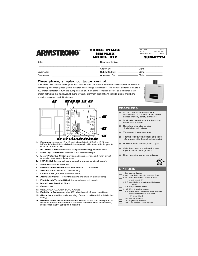
1 16 3 5 14 12
4
2
13
6 10 15 12 7 8 9 11
1.
Enclosure measures 12 x 10 x 6 inches (30.48 x 25.40 x 15.24 cm).
NEMA 4X (ultraviolet stabilized thermoplastic with removable flanges for outdoor or indoor use).
2.
IEC Motor Contactor controls pumps by switching electrical lines.
3.
Multi-Tap Transformer provides 120V control voltage.
4.
Motor Protective Switch provides adjustable overload, branch circuit protection and pump disconnect.
5.
HOA Switch for manual pump control (mounted on circuit board).
6.
Schematic/Wiring Diagram
7.
Green Pump Run Indicator Light mounted on circuit board.
8.
Alarm Fuse (mounted on circuit board).
9.
Control Fuse (mounted on circuit board).
10. Alarm and Control Power Indicators (mounted on circuit board).
11. Float Switch Terminal Block (mounted on circuit board).
12. Input Power Terminal Block
13. Ground Lug
STANDARD ALARM PACKAGE
14. Red Alarm Beacon provides 360° visual check of alarm condition.
15. Alarm Horn provides audio warning of alarm condition (83 to 85 decibel rating).
16. Exterior Alarm Test/Normal/Silence Switch allows horn and light to be tested or horn to be silenced in an alarm condition. Horn automatically resets once alarm condition is cleared.
FEATURES
■ Entire control system (panel and switches) is UL Listed to meet and/or exceed industry safety standards
■ Dual safety certification for the United
States and Canada
■ Complete with step-by-step
installation instructions
■ Three-year limited warranty
■ Thermal cutout/heat sensor auto reset
(for pumps with thermal switch leads)
■ Auxiliary alarm contact, form C type
■ Main disconnect - non-fused rotary
style, mounted through door.
■ Door mounted pump run indicator
OPTIONS
3A Alarm flasher
!" 4A Low level cutout - requires float.
!
4B Red low-level indicator & alarm must select 4A
!
5 E Seal failure circuit & red indicator
(2 wire)
8A Elapsed time meter
!
8C Event (cycle) counter
10A Clear inner swing-out door w/dead front (components mounted
on inner door)
10E Lockable latch
10G Lightning arrester
10K Anti-condensation heater
THREE PHASE - SIMPLEX MODEL 312
S.A. Armstrong Limited
23 Bertrand Avenue
Toronto, Ontario
Canada, M1L 2P3
Tel: (416) 755-2291
Fax: (416) 759-9101
Visit us at www.armstrongpumps.com
Armstrong Pumps Limited
Peartree Road, Stanway
Colchester, Essex
United Kingdom, C03 5JX
Tel: 01206-579491
Fax: 01206-760532
© S.A. Armstrong Limited 2000
Armstrong Pumps Inc.
93 East Avenue
Buffalo, New York
U.S.A. 14120-6594
Tel: (716) 693-8813
Fax: (716) 693-8970
Armstrong Darling Inc.
2200 Place Transcanadienne
Montreal, Quebec
Canada, H9P 2X5
Tel: (514) 421-2424
Fax: (514) 421-2436
®


