Product Specification
37406A
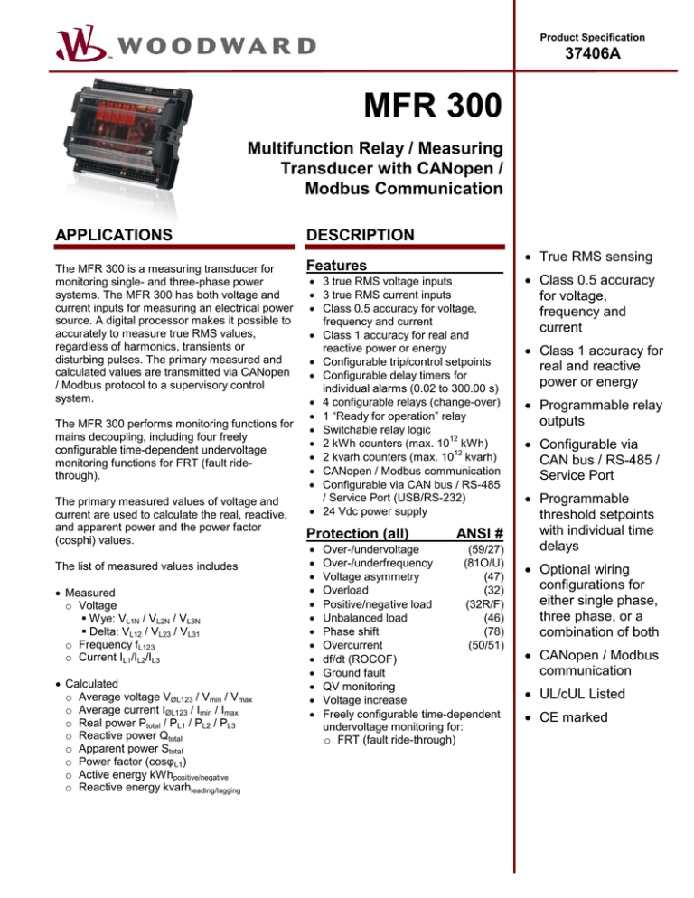
MFR 300
Multifunction Relay / Measuring
Transducer with CANopen /
Modbus Communication
APPLICATIONS
The MFR 300 is a measuring transducer for
monitoring single- and three-phase power
systems. The MFR 300 has both voltage and
current inputs for measuring an electrical power
source. A digital processor makes it possible to
accurately to measure true RMS values,
regardless of harmonics, transients or
disturbing pulses. The primary measured and
calculated values are transmitted via CANopen
/ Modbus protocol to a supervisory control
system.
The MFR 300 performs monitoring functions for
mains decoupling, including four freely
configurable time-dependent undervoltage
monitoring functions for FRT (fault ridethrough).
The primary measured values of voltage and
current are used to calculate the real, reactive,
and apparent power and the power factor
(cosphi) values.
The list of measured values includes
• Measured
o Voltage
Wye: VL1N / VL2N / VL3N
Delta: VL12 / VL23 / VL31
o Frequency fL123
o Current IL1/IL2/IL3
• Calculated
o Average voltage VØL123 / Vmin / Vmax
o Average current IØL123 / Imin / Imax
o Real power Ptotal / PL1 / PL2 / PL3
o Reactive power Qtotal
o Apparent power Stotal
o Power factor (cosφL1)
o Active energy kWhpositive/negative
o Reactive energy kvarhleading/lagging
DESCRIPTION
• True RMS sensing
Features
• 3 true RMS voltage inputs
• 3 true RMS current inputs
• Class 0.5 accuracy for voltage,
frequency and current
• Class 1 accuracy for real and
reactive power or energy
• Configurable trip/control setpoints
• Configurable delay timers for
individual alarms (0.02 to 300.00 s)
• 4 configurable relays (change-over)
• 1 “Ready for operation” relay
• Switchable relay logic
12
• 2 kWh counters (max. 10 kWh)
12
• 2 kvarh counters (max. 10 kvarh)
• CANopen / Modbus communication
• Configurable via CAN bus / RS-485
/ Service Port (USB/RS-232)
• 24 Vdc power supply
Protection (all)
•
•
•
•
•
•
•
•
•
•
•
•
•
ANSI #
Over-/undervoltage
(59/27)
Over-/underfrequency
(81O/U)
Voltage asymmetry
(47)
Overload
(32)
Positive/negative load
(32R/F)
Unbalanced load
(46)
Phase shift
(78)
Overcurrent
(50/51)
df/dt (ROCOF)
Ground fault
QV monitoring
Voltage increase
Freely configurable time-dependent
undervoltage monitoring for:
o FRT (fault ride-through)
• Class 0.5 accuracy
for voltage,
frequency and
current
• Class 1 accuracy for
real and reactive
power or energy
• Programmable relay
outputs
• Configurable via
CAN bus / RS-485 /
Service Port
• Programmable
threshold setpoints
with individual time
delays
• Optional wiring
configurations for
either single phase,
three phase, or a
combination of both
• CANopen / Modbus
communication
• UL/cUL Listed
• CE marked
SPECIFICATIONS
Accuracy ....................................................................................... Class 0.5
Power supply .......................................................... 12/24 Vdc (8 to 32 Vdc)
Intrinsic consumption ....................................................................max. 5 W
Ambient temperature (operation) ................ -20 °C (-4 °F) / 70 °C (158 °F)
Ambient temperature (storage) ................. -40 °C (-40 °F) / 85 °C (185 °F)
Ambient humidity...................................................... 95 %, non-condensing
Voltage ........... Rated value /∆: [1] 69/120 Vac or [7] 400/690 Vac
or [7] 600 Vac
Rated voltage Vph-ground: [1] 150 Vac
or [7] 862 Vac
Max. cont. voltage Vph-ph: [1] 150 Vac
Rated surge voltage: [1] 2.5 kV
or [7] 6.0 kV
Measuring frequency ................................................................. 45 to 65 Hz
Linear measuring range ............................................................ 1.25 × Vrated
Input resistance ........................................................................ [1] >0.5 MΩ
[7] >2.0 MΩ
Max. power consumption per path ................................................... 0.15 W
Current (Irated) ................................................................. [1] ../1 A, [5] ../5 A
Linear measuring range .................................................................. 3 × Irated
Max. power consumption per path ............................................... < 0.15 VA
Rated short-time current (1 s) ................................... [1] 10 Aac, [5] 50 Aac
Relay outputs ................................................................................ isolated
Contact type ..............................................................Form C (change-over)
Contact material ............................................................................... AgCdO
Load (GP) ......................................................................2.00 Aac@250 Vac
....................2.00 Adc@24 Vdc / 0.36 Adc@125 Vdc / 0.18 Adc@250 Vdc
Pilot duty (PD) ..............................................................................................
....................1.00 Adc@24 Vdc / 0.22 Adc@125 Vdc / 0.10 Adc@250 Vdc
Housing ....................................................... Type Extrusion profile UM122
for DIN rail mounting
Dimensions ...................................................................146 × 128 × 50 mm
Connection ................................................ screw/plug terminals depending
on connector 2.5 mm² (14 AWG)
Protection system................................................................................. IP20
Weight .................................................................................... approx. 300 g
Disturbance test (CE) .......... tested according to applicable EN guidelines
Listings ................................. UL/cUL listed (File No.: E231544), GOST-R
DIMENSIONS
PART NUMBERS
Model
MFR300-11M
MFR300-15M
MFR300-71M
MFR300-75M
MFR300-75M/SU03
MFR300-75M/K28
Rated PT secondary
100 Vac [1]
690 Vac [7]
100 Vac [1]
690 Vac [7]
690 Vac [7]
690 Vac [7]
Rated CT secondary
../1 A [1]
../5 A [5]
../1 A [1]
../5 A [5]
../5 A [5]
../5 A [5]
Mounting
DIN rail
DIN rail
DIN rail
DIN rail
DIN rail
DIN rail
Part Number (P/N)
8444-1089
8444-1090
8444-1091
8444-1092
8444-1093
8444-1094
WIRING DIAGRAM
International
Woodward
PO Box 1519
Fort Collins CO, USA
80522-1519
1000 East Drake Road
Fort Collins CO 80525
Ph: +1 (970) 482-5811
Fax: +1 (970) 498-3058
TYPICAL APPLICATIONS
General Application
In this general application the device is used as a
transducer with monitoring functions. The control does not
operate any breaker.
•
•
Europe
Woodward GmbH
Handwerkstrasse 29
70565 Stuttgart, Germany
Ph: +49 (0) 711 789 54-0
Fax: +49 (0) 711 789 54-100
email: stgtinfo@woodward.com
Distributors & Service
Woodward has an international
network of distributors and
service facilities. For your
nearest representative, call the
Fort Collins plant or see the
Worldwide Directory on our
website.
PLC measuring data V, f, I, Pact, Preact
Monitoring V, f, I, Pact, Preact
Generator Application
In this generator related application the device is used as a
transducer with monitoring functions. The control can be
used to open a breaker.
www.woodward.com/power
For more information contact:
•
•
Generator measuring data V, f, I, Pact, Preact
Monitoring V, f, I, Pact, Preact
Mains Application
Subject to technical modifications.
This document is distributed for
informational purposes only. It is not
to be construed as creating or
becoming part of any Woodward
Governor Company contractual or
warranty obligation unless expressly
stated in a written sales contract.
We appreciate your comments about
the content of our publications.
Please send comments including the
document number below to
stgt-doc@woodward.com
© Woodward
All Rights Reserved
37406A - 2012/3/Stuttgart
In this mains related application the device is used as a
transducer with monitoring functions. The control can be
used to open a breaker.
•
•
Mains measuring data V, f, I, Pact, Preact
Monitoring V, f, I, Pact, Preact


