EVALUATION BOARD DATA SHEET
EV143
Evaluation Board for the AAT1217
600mA, 1.2 MHz Micropower Synchronous Step-Up Converter
Introduction
The AAT1217 is a 1.2MHz constant frequency, current mode PWM step-up converter. It can supply a 3.3V output voltage at 100mA from a single AA cell. The device integrates a main switch and a synchronous rectifier for high efficiency
without an external Schottky diode. A switching frequency of 1.2MHz allows the use of small, low profile inductors and
ceramic capacitors. This demo board is designed for evaluating the AAT1217. The device can supply 400mA to a 3.3V
load from a two AA cell input. Every demo board circuit is fully tested and supported with test data before shipping.
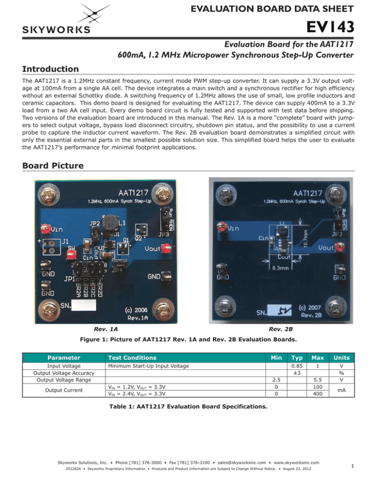
Two versions of the evaluation board are introduced in this manual. The Rev. 1A is a more “complete” board with jumpers to select output voltage, bypass load disconnect circuitry, shutdown pin status, and the possibility to use a current
probe to capture the inductor current waveform. The Rev. 2B evaluation board demonstrates a simplified circuit with
only the essential external parts in the smallest possible solution size. This simplified board helps the user to evaluate
the AAT1217’s performance for minimal footprint applications.
Board Picture
Rev. 1A
Rev. 2B
Figure 1: Picture of AAT1217 Rev. 1A and Rev. 2B Evaluation Boards.
Parameter
Input Voltage
Output Voltage Accuracy
Output Voltage Range
Output Current
Test Conditions
Min
Minimum Start-Up Input Voltage
VIN = 1.2V, VOUT = 3.3V
VIN = 2.4V, VOUT = 3.3V
Typ
Max
Units
0.85
±3
1
V
%
V
2.5
0
0
5.5
100
400
mA
Table 1: AAT1217 Evaluation Board Specifications.
Skyworks Solutions, Inc. • Phone [781] 376-3000 • Fax [781] 376-3100 • sales@skyworksinc.com • www.skyworksinc.com
202282A • Skyworks Proprietary Information • Products and Product Information are Subject to Change Without Notice. • August 22, 2012
1
EVALUATION BOARD DATA SHEET
EV143
Evaluation Board for the AAT1217
600mA, 1.2 MHz Micropower Synchronous Step-Up Converter
L1
4.7µH
D1
MBR0520
JP2
JP4
1
SW
6
VIN
CIN
4.7µF
VIN
5
VOUT
AAT1217
4
3
FB
SHDN
Q1
Si 2305DS
R4
510k
VOUT
R1
1. 02M
C OUT
4.7µF
JP1
GND
2
R2A:1002k
B: 696 k
C: 604 k
D: 324 k
Q2
2N 3904
R3
510k
ON / OFF Control
(JP3)
2.5V
3.0V
3.3V
5.0V
Figure 2: AAT1217 Evaluation Board Rev. 1A Schematic.
L1
4.7µH
C3
100pF
(Opt )
VIN
CIN
4.7µF
D1
MBR0520
1
SW
6
VIN
VOUT
5
AAT1217
4
FB
SHDN
GND
3
VOUT
R1
1. 02M
C OUT
4.7µF
R2
2
R2A:1002k
B:696k
C:604k
D:324k
2.5V
3.0V
3.3V
5.0V
ON / OFF Control
(JP3)
Figure 3: AAT1217 Evaluation Board Rev. 2B Schematic.
PCB Layout
The AAT1217 typically operates at 1.2MHz. This is a significantly high frequency for DC-DC converters. For satisfactory
performance, PCB layout is important with high operational frequencies. The PCB traces should be as wide and as short
as possible. The inductor, input capacitor, and output capacitor should be as close as possible to the AAT1217. The
feedback and shutdown pin PCB traces should avoid proximity to large AC signals, such as the power inductor and
switching nodes. The optional rectifier diode (D1 in Figure 4 and Figure 7) can improve efficiency and alleviate the stress
2
Skyworks Solutions, Inc. • Phone [781] 376-3000 • Fax [781] 376-3100 • sales@skyworksinc.com • www.skyworksinc.com
202282A • Skyworks Proprietary Information • Products and Product Information are Subject to Change Without Notice. • August 22, 2012
EVALUATION BOARD DATA SHEET
EV143
Evaluation Board for the AAT1217
600mA, 1.2 MHz Micropower Synchronous Step-Up Converter
on the integrated power MOSFET. The diode should also be close to the inductor and the chip to form the shortest possible switching loop. While a two layer PCB layout is adequate for most applications, large multi-layer ground planes
are ideal for high power applications. A large area of copper has lower resistance and would help dissipate heat from
the AAT1217. The two demo boards described in this manual are four layer PCBs with two internal ground layers. The
converter’s ground should join the system ground to which it supplies power at one point only.
Figure 4: AAT1217 Evaluation Board
Rev. 1A PCB Top Side.
Figure 5: AAT1217 Evaluation Board
Rev. 1A PCB Bottom Side.
Figure 6: AAT1217 Evaluation Board
R
ev. 2B PCB Top Side.
Figure 7: AAT1217 Evaluation Board
Rev. 2B PCB Bottom Side.
Skyworks Solutions, Inc. • Phone [781] 376-3000 • Fax [781] 376-3100 • sales@skyworksinc.com • www.skyworksinc.com
202282A • Skyworks Proprietary Information • Products and Product Information are Subject to Change Without Notice. • August 22, 2012
3
EVALUATION BOARD DATA SHEET
EV143
Evaluation Board for the AAT1217
600mA, 1.2 MHz Micropower Synchronous Step-Up Converter
Evaluation Setup (see Figures 4, 6, and 8)
Jumper Setting
JP1
JP2
JP3
Description
Output voltage selector. R2A:2.5V, R2B:3V, R2C:3.3V, R2D:5V (Rev.1A only)
Connection between inductor and SW pin, Inductor current can be probed here (Rev.1A Only)
Run/Shutdown selector
Connection between VOUT pin and board output. Q1 and Q2 are designed to disconnect load from the
VOUT pin when the device is shut down. Shorting this jumper will bypass this circuit and connect the
VOUT pin to board output directly. (Rev.1A only)
JP4
Operating the Evaluation Board
Apply a DC power supply and DC voltmeter across the input voltage terminals. Set the voltage at least 0.5V below the
output voltage, otherwise the board may not be able to work properly.
Connect a dummy load between VOUT and GND. The board can operate with both electronic and resistor loads. When
the load current is too high, the device may begin to limit the inductor current, and thus the output voltage may
drop.
Since the body diode of the integrated P-channel synchronous rectifier MOSFET exists from the SW pin to the VOUT
pin, when VOUT < VIN, current can flow from VIN to VOUT. This happens when the device is shut down. On the Rev.1A
board, a simple circuit has been added to isolate the load from VIN; during shutdown, the Q2 collector pin is pulled low
to ground, or logic low, which will shut down Q1. In normal operation, the base pin of Q2 is logic high, thus the gate
of Q2 is low and Q1 is conducting. The user can bypass this function by connecting JP4.
Load and Line Regulation
1. Before beginning operation, set JP1 to the VOUT voltage position (R2A = 2.5V, R2B = 3.0V, R2C = 3.3V and R2D
= 5.0V) and set JP3 from SHDN to RUN.
2. Vary the load and the input voltage while monitoring the output voltage.
3. The output voltage as measured at the output terminals of the evaluation boards should not vary by more than
±3% of the nominal voltage.
+A+
+
-
-
+
V
+
V
-
A
+
Load
-
Figure 8: AAT1217 Connection Diagram.
4
Skyworks Solutions, Inc. • Phone [781] 376-3000 • Fax [781] 376-3100 • sales@skyworksinc.com • www.skyworksinc.com
202282A • Skyworks Proprietary Information • Products and Product Information are Subject to Change Without Notice. • August 22, 2012
EVALUATION BOARD DATA SHEET
EV143
Evaluation Board for the AAT1217
600mA, 1.2 MHz Micropower Synchronous Step-Up Converter
Component
Part Number
Description
U1
L1
CIN, COUT
D1
Q1
Q2
R1, R2A, R3
R2B
R2C
R2D
R4, R5
AAT1217
CDRH5D16NP-4R7NC
GRM42-6X7R475K16PT
MBR0520LT1
Si2305DS (optional)
2N3904
ERJ3EKF1004V
ERJ3EKF6983V
ERJ3EKF6043V
ERJ3EKF3243V
ERJ3EKF5103V
Manufacturer
1.2 MHz, 600mA Micropower Synchronous Step-Up Converter
Inductor 4.7µH 2.15A
Ceramic Cap 4.7µF16V X7R 1206
Schottky Diode 0.5A 20V
P-Channel 1.25-W, 1.8-V (G-S) MOSFET
NPN General Purpose Amplifier
Res 1MΩ 1/16W 1% 0603
Res 698kΩ 1/16W 1% 0603
Res 604KΩ 1/16W 1% 0603
Res 324KΩ 1/16W 1% 0603
Res 510KΩ 1/16W 1% 0603
Skyworks
Sumida
Murata
Onsemi
Vishay
Fairchild
Panasonic
Panasonic
Panasonic
Panasonic
Panasonic
Table 2: AAT1217 Evaluation Board Rev. 1A Bill of Materials.
Component
Part Number
Description
C3
C5
CIN
COUT
D1
L1
R1
R2
R3
GRM1885C1H101JA01
LLL185R71A104MA01
GRM219R61A475KE19
GRM219R61A475KE19
MBR0520LT1
CDRH2D09-4R7NC
ERJ3EKF1004V
ERJ3EKF6043V
ERJ3EKF1004V
U1
AAT1217
Ceramic Cap 100pF 50V C0G 0603
Ceramic Cap 100nF 10V X7R 0603
Ceramic Cap 4.7μF 10V X5R 0805
Ceramic Cap 4.7μF 10V X5R 0805
Schottky Diode 0.5A 20V
4.7µH
Res 1MΩ 1/16W 1% 0603
Res 604kΩ 1/16W 1% 0603
Res 1MΩ 1/16W 1% 0603
1.2MHz, 600mA Micropower Synchronous
Step-Up Converter
Manufacturer
Murata
Murata
Murata
Murata
Onsemi
Sumida
Panasonic
Panasonic
Panasonic
Skyworks
Table 3: AAT1217 Evaluation Board Rev. 2B Bill of Materials.
Output Voltage Setting
The reference voltage of AAT1217 is 1.23V. The user can change R1 and R2 to obtain needed output voltage by this
formula:
VOUT =
R1 + R2
· 1.23V
R2
The maximum VOUT is 5.5V.
Skyworks Solutions, Inc. • Phone [781] 376-3000 • Fax [781] 376-3100 • sales@skyworksinc.com • www.skyworksinc.com
202282A • Skyworks Proprietary Information • Products and Product Information are Subject to Change Without Notice. • August 22, 2012
5
EVALUATION BOARD DATA SHEET
EV143
Evaluation Board for the AAT1217
600mA, 1.2 MHz Micropower Synchronous Step-Up Converter
Copyright © 2012 Skyworks Solutions, Inc. All Rights Reserved.
Information in this document is provided in connection with Skyworks Solutions, Inc. (“Skyworks”) products or services. These materials, including the information contained herein, are provided by Skyworks as a
service to its customers and may be used for informational purposes only by the customer. Skyworks assumes no responsibility for errors or omissions in these materials or the information contained herein. Skyworks may change its documentation, products, services, specifications or product descriptions at any time, without notice. Skyworks makes no commitment to update the materials or information and shall have no
responsibility whatsoever for conflicts, incompatibilities, or other difficulties arising from any future changes.
No license, whether express, implied, by estoppel or otherwise, is granted to any intellectual property rights by this document. Skyworks assumes no liability for any materials, products or information provided hereunder, including the sale, distribution, reproduction or use of Skyworks products, information or materials, except as may be provided in Skyworks Terms and Conditions of Sale.
THE MATERIALS, PRODUCTS AND INFORMATION ARE PROVIDED “AS IS” WITHOUT WARRANTY OF ANY KIND, WHETHER EXPRESS, IMPLIED, STATUTORY, OR OTHERWISE, INCLUDING FITNESS FOR A PARTICULAR
PURPOSE OR USE, MERCHANTABILITY, PERFORMANCE, QUALITY OR NON-INFRINGEMENT OF ANY INTELLECTUAL PROPERTY RIGHT; ALL SUCH WARRANTIES ARE HEREBY EXPRESSLY DISCLAIMED. SKYWORKS DOES
NOT WARRANT THE ACCURACY OR COMPLETENESS OF THE INFORMATION, TEXT, GRAPHICS OR OTHER ITEMS CONTAINED WITHIN THESE MATERIALS. SKYWORKS SHALL NOT BE LIABLE FOR ANY DAMAGES, INCLUDING BUT NOT LIMITED TO ANY SPECIAL, INDIRECT, INCIDENTAL, STATUTORY, OR CONSEQUENTIAL DAMAGES, INCLUDING WITHOUT LIMITATION, LOST REVENUES OR LOST PROFITS THAT MAY RESULT FROM
THE USE OF THE MATERIALS OR INFORMATION, WHETHER OR NOT THE RECIPIENT OF MATERIALS HAS BEEN ADVISED OF THE POSSIBILITY OF SUCH DAMAGE.
Skyworks products are not intended for use in medical, lifesaving or life-sustaining applications, or other equipment in which the failure of the Skyworks products could lead to personal injury, death, physical or environmental damage. Skyworks customers using or selling Skyworks products for use in such applications do so at their own risk and agree to fully indemnify Skyworks for any damages resulting from such improper
use or sale.
Customers are responsible for their products and applications using Skyworks products, which may deviate from published specifications as a result of design defects, errors, or operation of products outside of published parameters or design specifications. Customers should include design and operating safeguards to minimize these and other risks. Skyworks assumes no liability for applications assistance, customer product
design, or damage to any equipment resulting from the use of Skyworks products outside of stated published specifications or parameters.
Skyworks, the Skyworks symbol, and “Breakthrough Simplicity” are trademarks or registered trademarks of Skyworks Solutions, Inc., in the United States and other countries. Third-party brands and names are for
identification purposes only, and are the property of their respective owners. Additional information, including relevant terms and conditions, posted at www.skyworksinc.com, are incorporated by reference.
6
Skyworks Solutions, Inc. • Phone [781] 376-3000 • Fax [781] 376-3100 • sales@skyworksinc.com • www.skyworksinc.com
202282A • Skyworks Proprietary Information • Products and Product Information are Subject to Change Without Notice. • August 22, 2012

