microtechnologies incorporated
advertisement

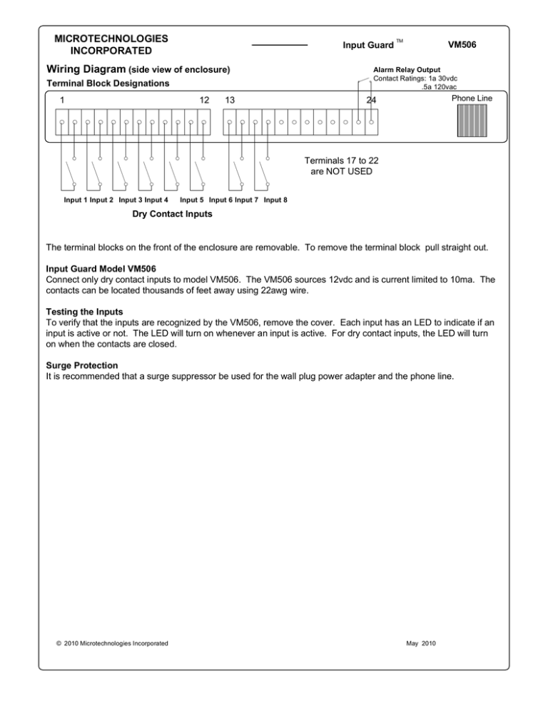
MICROTECHNOLOGIES INCORPORATED Input Guard Wiring Diagram (side view of enclosure) 12 13 1v VM506 Alarm Relay Output Contact Ratings: 1a 30vdc .5a 120vac Terminal Block Designations 1 TM Phone Line 24 v Terminals 17 to 22 are NOT USED Input 1 Input 2 Input 3 Input 4 Input 5 Input 6 Input 7 Input 8 Dry Contact Inputs The terminal blocks on the front of the enclosure are removable. To remove the terminal block pull straight out. Input Guard Model VM506 Connect only dry contact inputs to model VM506. The VM506 sources 12vdc and is current limited to 10ma. The contacts can be located thousands of feet away using 22awg wire. Testing the Inputs To verify that the inputs are recognized by the VM506, remove the cover. Each input has an LED to indicate if an input is active or not. The LED will turn on whenever an input is active. For dry contact inputs, the LED will turn on when the contacts are closed. Surge Protection It is recommended that a surge suppressor be used for the wall plug power adapter and the phone line. © 2010 Microtechnologies Incorporated May 2010 MICROTECHNOLOGIES INCORPORATED Input Guard Wiring Diagram (side view of enclosure) TM VM506LV Alarm Relay Output Terminal Block Designations 1 12 13 1v v Terminals 17 to 22 are NOT USED 24 VAC Input 2 Input 1 24 VAC Phone Line 24 t 24 VDC Input 3 Input 4 Input 5 Input 6 Input 7 Input 8 The Inputs are switch selectable to be dry contact or 24v ac/dc inputs The terminal blocks on the front of the enclosure are removable. To remove the terminal block pull straight out. Input Guard Model VM506LV Each input of the VM506LV is switch selectable to be either a 24vac/dc input or a dry contact input. The VM506LV comes shipped from the factory with all switches set to the dry contact input type. Setting the Input Type Select Switches ·Turn off the power to the unit. ·Remove the four screws holding the cover of the VM506LV. ·The eight switches are located on the center of the board and there is one for each input. Input 1 Type Select ·Switch is on the far left, and Input 8 Type Select Switch is on the far right. ·For dry contact inputs, move the switch to the UP position. ·For 24vac/dc inputs, move the switch to the DOWN position. For the example above, the Input Type Select Switches for inputs 1, 5, 6, 7, 8 must be in the up position. For inputs 2,3 and 4 the switches must be in the down position. Testing the Inputs To verify that the inputs are recognized by the VM506LV, remove the cover. Each input has an LED to indicate if an input is active or not. The LED will turn on whenever an input is active. For dry contact inputs, the LED will turn on when the contacts are closed. For 24vac/dc inputs, the LED will turn on whenever the voltage is applied. Surge Protection It is recommended that a surge suppressor be used for the wall plug power adapter and the phone line. © 2006 Microtechnologies Incorporated January 2006


