AME20213 HOMEWORK ASSIGNMENT NO. 4 SOLUTIONS
advertisement

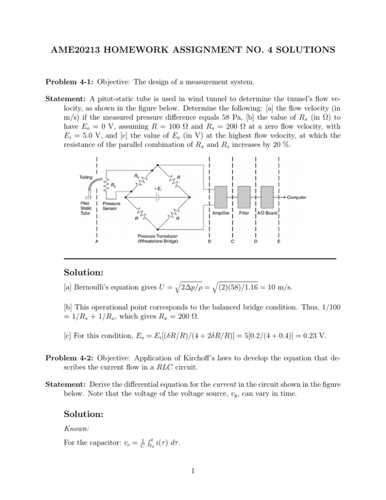
AME20213 HOMEWORK ASSIGNMENT NO. 4 SOLUTIONS Problem 4-1: Objective: The design of a measurement system. Statement: A pitot-static tube is used in wind tunnel to determine the tunnel’s flow velocity, as shown in the figure below. Determine the following: [a] the flow velocity (in m/s) if the measured pressure difference equals 58 Pa, [b] the value of Rx (in Ω) to have Eo = 0 V, assuming R = 100 Ω and Rs = 200 Ω at a zero flow velocity, with Ei = 5.0 V, and [c] the value of Eo (in V) at the highest flow velocity, at which the resistance of the parallel combination of Rx and Rs increases by 20 %. Solution: [a] Bernoulli’s equation gives U = q 2∆p/ρ = q (2)(58)/1.16 = 10 m/s. [b] This operational point corresponds to the balanced bridge condition. Thus, 1/100 = 1/Rs + 1/Rx , which gives Rx = 200 Ω. [c] For this condition, Eo = Ei [(δR/R)/(4 + 2δR/R)] = 5[0.2/(4 + 0.4)] = 0.23 V. Problem 4-2: Objective: Application of Kirchoff’s laws to develop the equation that describes the current flow in a RLC circuit. Statement: Derive the differential equation for the current in the circuit shown in the figure below. Note that the voltage of the voltage source, vg , can vary in time. Solution: Known: For the capacitor: vc = 1 C Rt to i(τ ) dτ . 1 R + Vg − L C di For the inductor: vc = L dt . Analysis: By applying Kirchoff’s voltage law: 1 Zt di Ri + i(τ ) dτ + vc (to ) + L = vg . C to dt Differentiate the above equation to get, L d2 i di 1 dvg +R + i = . 2 dt dt C dt Divide the above equation by L, ⇒ d2 i R di 1 1 dvg + + i = . dt2 L dt CL L dt This equation is a second order ordinary differential equation that can be solved for i. Problem 4-3: Objective: Application of Kirchoff’s laws to develop the equation that describes the voltage across a capacitor in a RC circuit. Statement: The circuit shown below is used for a flash in a camera. When the flash is switched on, the 9 V source is connected into the circuit. The capacitor then charges toward the source voltage through the resistor. During this charging time, no current flows through the camera flash. Derive the differential equation for the capacitor voltage, vC . Solution: 2 R a C Camera Flash Vs = 9 V Known: For the capacitor: Ic = C At the nodes: Pn 1 dv . dt i = 0. Analysis: By applying Kirchoff’s current law at point a: C dvc vc − Vs + = 0. dt R This can be rearranged as: dvc vc − Vs + = 0. dt RC This equation is a first order differential equation in vc . Problem 4-4: Objective: The design of a measurement system. Chapter 4, HOMEWORK Problem No. 3 Solution: Known: Eo Ei 1 = ( R1R+R − 2 R3 ) R3 +R4 Schematic: 3 i1 i2 R1 - +i R2 + R3 Ei Eo + R4 i4 i3 Figure 1: The Wheatstone bridge configuration. Analysis: [a] R = Ro · exp[β( T1 − R1 = R Eo Ei = ³ 1 )] To and R2 = R3 = R4 = Ro = 1000 Ω. R1 R1 +R2 − R3 R3 +R4 ´ ½ =− ¾ exp[β( T1 − T1 )] o 1000+exp[β( T1 − T1 )] − o 1 2 . At T = 400 ◦ C = 673.15 K, To = 27 ◦ C = 300.15 K and β = 3500/K, Eo Ei = -0.498. Note that the resistance of a thermistor decreases with increasing temperature. This leads to a negative output voltage when used as such (as R1 ) in this circuit. [b] 0 −0.05 −0.1 −0.15 o E /E i −0.2 −0.25 −0.3 −0.35 −0.4 −0.45 −0.5 300 350 400 450 500 550 Temperature, K 600 650 700 750 800 [c] From the plot, it is seen that the normalized output is approximately linear from To ≤ T ≤∼340 K. [d] The normalized output becomes relatively insensitive to temperature change above T ≈ 500 K. 4


