Scope of this document
The scope of this document is to explain in easily understandable language
the necessary steps to install the PDS-70mr and assure peak performance.
Its intended use is for reference only, by persons who are fully qualified.
This document should never be considered a substitute for any provisions
of a regulation or state and / or local code.
PDS-70mr 24V
i n s t a l l a t i o n
i n s t r u c t i o n s
PRE-PROGRAMMED, DMX, or ETHERNET CONTROL
Philips Solid-State Lighting Solutions, Inc.
3 Burlington Woods Drive
Burlington, Massachusetts 01803 USA
Tel 888.Full.RGB
Tel 617.423.9999
Fax 617.423.9998
www.colorkinetics.com
ITEM # 109-000018-00 (Pre-programmed)
109-000018-01 (DMX)
109-000018-02 (Ethernet)
Copyright © 2008 Philips Solid-State Lighting Solutions, Inc. All rights reserved.
Chromacore, Chromasic, CK, the CK logo, Color Kinetics, the Color Kinetics logo, ColorBlast,
ColorBlaze, ColorBurst, ColorGraze, ColorPlay, ColorReach, DIMand, EssentialWhite, eW,
iColor, iColor Cove, IntelliWhite, iW, iPlayer, Light Without Limits, Optibin, and Powercore
are either registered trademarks or trademarks of Philips Solid-State Lighting Solutions, Inc. in
the United States and/or other countries. All other brand or product names are trademarks
or registered trademarks of their respective owners.
All other brand or product names are trademarks or registered trademarks of their respective owners
PUB-000110-00 Rev 03
Specifications subject to change without notice. Refer to www.colorkinetics.com for the most
recent version.
This Installation Instruction contains important information on installing
and using your new PDS-70mr. Please read it carefully and save it for future
reference.
Included in this box
•P
ower / data supply with cover, gasket, attaching screws, and NPT
threaded seal plugs
• Installation Instructions
Additional items needed
• Mounting hardware and tools
• 14 – 18 AWG, 2-conductor jacketed cable (Non-conduit applications)
• Standard strain relief cable clamps (Indoor applications)
• Water-tight conduit and fittings (as required per local codes)
• Electronic grade RTV Silicone (UL recognized) to seal conduit
connections as required
• 5/16 in hex wrench or adjustable wrench for seal plugs
• Wire nuts
caution: Ensure
proper installation for outdoor applications to maintain
NEMA 4 ratings. Failure to do so will result in property damage and void
the warranty.
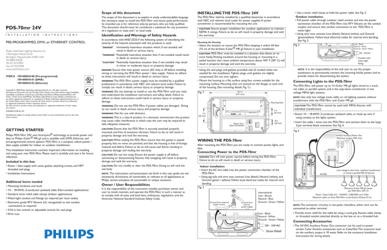
Mounting the Housing
• S elect the location to mount the PDS-70mr, keeping it within 50 feet
(15 m) of the farthest iColor® MR g2 fixture in your installation.
•U
sing the seal plugs and gaskets provided, seal all conduit holes not
needed for the installation. Tighten plugs until gaskets are slightly
compressed. Do not over tighten.
• Mount the housing to a flat surface using four screws suitable for the
mounting surface. Mounting slots are located on the flanges at each end
of the housing. (See mounting details, Fig. 1.)
Fig. 1
8.3 in
(211 mm)
1 in
(25 mm)
2 in
(50 mm)
Power Out /
Data Connection
caution: Do
warranty.
not modify or alter the PDS-70mr. Doing so will void the
note:
The instructions and precautions set forth in this user guide are not
necessarily all-inclusive, all conceivable, or relevant to all applications as
Philips cannot anticipate all conceivable or unique situations.
Owner / User Responsibilities
It is the responsibility of the contractor, installer, purchaser, owner, and
user to install, maintain, and operate the PDS-70mr in such a manner as
to comply with all state and local laws, ordinances, regulations, and the
American National Standard Institute Safety Code.
100 – 240 VAC
Conduit with
water-tight
fitting
It is the responsibility of the end user to use the proper
conductors to permanently connect the incoming facility power, and to
provide means for disconnecting the system.
note:
Connecting Lights to the PDS-70mr
The PDS-70mr will power up to 14 iColor MR g2 lights wired to a track,
rail, cable, or parallel system, and is the step-down transformer in low
voltage MR16 light systems.
note: Use
Mounting Slots
that the PDS-70mr is securely attached, properly
mounted, and free of excessive vibration. Failure to do so will result in
property damage and void the warranty.
sealing the PDS-70mr, ensure that the gasket is seated
properly, that no wires are pinched, and that the housing is free of foreign
material and debris. Failure to do so will cause seal failure resulting in
property damage and voiding the warranty.
caution: Do not hot swap. Ensure the power supply is off before
connecting or disconnecting fixtures. Hot swapping will result in property
damage and void the warranty.
Line - Black
Neutral - White
Ground - Green / Yellow
Fig 3
must be installed in a location that allows air to
move freely. Packing insulation around the housing or mounting in a
sealed location that raises ambient temperature above 104º F (40º C) will
result in property damage and void the warranty.
caution: Ensure
caution: When
• Use a strain relief clamp to hold the power cable. See Fig. 2.
Outdoor installation:
• Pull power cable through outdoor rated conduit and into the power
connection chamber of the PDS-70mr. Use RTV Silicone on the conduit
coupler and ensure that conduit connection to the PDS-70mr is
water-tight.
• Using wire nuts, connect Line (black), Neutral (white), and Ground
(green/yellow). Follow local electrical codes for internal wire bending.
See Fig. 3.
caution: PDS-70mr
.8 in
(20 mm)
DMX
OUT
Philips PDS-70mr 24V uses Smartjuice® technology to provide power and
data to Philips iColor® MR g2 and is available with DMX, Ethernet, and
pre-programmed control options. PDS-70mr is a compact, robust power /
data supply suitable for indoor or outdoor installations.
In accordance with ANSI Z535.4 the following system of identifying the
severity of the hazards associated with the products is used:
“danger” Imminently hazardous situation which, if not avoided, will
result in death or serious injury.
“warning”Potentially hazardous situation that, if not avoided, could result
in death or serious injury.
“caution” Potentially hazardous situation that, if not avoided, may result
in minor or moderate injury or property damage.
danger: Ensure that main power source (AC line) is off before installing,
wiring, or servicing the PDS-70mr power / data supply. Failure to adhere
to these instructions will result in death or serious injury.
warning: The PDS-70mr power supply must be installed by a qualified
professional in accordance with NEC and relevant local codes. Failure to
comply can result in death, serious injury, or property damage.
warning: Do not attempt to install or use the PDS-70mr until you read
and understand the installation instructions and safety labels. Failure to
adhere to these instructions could result in serious injury or property
damage.
warning: Do not use the PDS-70mr if power cables are damaged. Doing
so can result in death, serious injury, and property damage.
warning: Not for use with dimmers.
warning: This is a class A product. In a domestic environment this product
may cause radio interference in which case the user may be required to
take adequate measures.
The PDS-70mr shall be installed by a qualified electrician in accordance
with NEC and relevant local codes for power supplies. A power
screwdriver is recommended for mounting the unit.
DMX/ETHERNET
IN
Getting Started
Identification and Warnings of Safety Hazards
INSTALLING THE PDS-70mr 24V
only low voltage track, cable, or rail lighting systems without
transformers with the PDS-70mr and iColor MR g2.
caution: The
PDS-70mr cannot be used with MR16 fixtures with
individual transformers.
• Attach 14 – 18 AWG 2-conductor jacketed cable, or hook-up wire if
using conduit, to the lights system.
• Insert the cable / wires into the PDS-70mr and connect them to the large
2-pin terminal block connector. See Fig. 4.
Fig 4
24 VDC Auxiliary Power Out
Maximum output: 10W max.
WIRING THE PDS-70mr
After mounting the PDS-70mr, you are ready to connect power, lights, and
data.
OUTPUT
Connecting Power to the PDS-70mr
danger: Turn
off main power source before wiring the PDS-70mr.
Failure to do so will result in death or serious injury.
OUTPUT
Ground from external
power source.
Ground from
internal
power supply
Line - Black
Neutral - White
Ground - Green / Yellow
100 – 240 VAC
Strain Relief
AUX
To Lights
Indoor installation:
• Insert the AC line cable into the power connection chamber of the
PDS-70mr.
• Using pig tails and wire nuts, connect Line (black), Neutral (white), and
Ground (green / yellow). Follow local electrical codes for internal wire
bending.
Fig. 2
International:
Line - Brown
Neutral - Blue
Ground - Green / Yellow
- +
DMX/ETHERNET
IN
DMX
OUT
24 VDC
Low voltage 2-wire track (without transformer)
or wired in parallel MR-16 fixtures
Maximum iColor MR g2 Lamps
per PDS-70mr 24V: 14
Power / Data Cable (14 – 18 AWG / 2.08-0.823 mm2 CSA)
Maximum cable run from PDS-70mr to last fixture: 50 feet (15 m)
note: The
connector circuitry is non-polar; therefore, either wire can be
connected to either terminal.
• Provide strain relief for the cable by using a cord grip, Romex cable clamp,
or threaded conduit attached directly to the box or to a threaded hub.
Connecting Accessories
• The 24 VDC Auxiliary Power Out connector can be used to power
certain Color Kinetics accessories such as ColorDial. The maximum load
on the auxiliary output is 10 watts. Refer to the accessory Installation
Instructions for wiring details.
warning: Use care when setting the pre-programmed effect. Do not allow
jewelry, clothing, or fingers to come in contact with sensitive circuitry of
line voltage wirings.
Addressing the Lights
• Use Light System Composer (LSC) to discover and address lights in you
system. Refer the LSC user guide for complete addressing instructions.
Sealing the PDS-70mr
•A
fter all the power and data connections have been made, and all conduit
holes are water-tight, replace the cover and attach with provided screws.
Tighten screws to 8 to 10 in / lbs.
note: Before attaching cover, ensure gasket is seated properly and
that no wires are pinched.
Fig. 6
OUTPUT
•L
ight Type: Set the toggle switch to position 1. Position 2 and 3 are
reserved for other products. See Fig. 5.
note: Before engaging power, set the light type using the toggle
switch. If Light Type is changed after power is engaged, the power
supply must be power cycled in order to recognize the change.
DMX/ETHERNET
IN
AUX
DMX
OUT
Mapping the Lights
• After installing the iColor MR g2 lighting system using the PDS-70mr,
with DMX or Ethernet control, map the lights in the system using Color
Kinetics Light System Manager or ColorPlay software.
note: With the exception of the Chasing Rainbow effect, when using
the PDS-70mr with pre-programmed control, light addressing is not
necessary.
• Once the power/data supplies and lights have been mapped, then you
are ready to begin designing shows using Light System Composer or
ColorPlay software.
For complete instructions for creating light shows, refer to the user
guide for your software.
Terminator
DMX IN
(CAT-5 / RJ45)
Fig. 5
100 – 240 VAC
1 - iColor MR g2
2 - OTHER PRODUCTS
3 - FUTURE PRODUCTS
OUTPUT
OUTPUT
AUX
AUX
OPTIONS
DMX/ETHERNET
IN
SPEED
MODE
DMX/ETHERNET
IN
DMX
OUT
Short-Circuit Protection
DMX
OUT
DMX OUT
DMX/ETHERNET
IN
DMX IN
(CAT-5 / RJ45)
DMX
OUT
The PDS-70mr 24V power / data supply is equipped with short-circuit
protection. In the event of a fault, you will receive a steady red indicator.
Correct the cause of the fault and then power cycle the PDS-70mr 24V.
note: When power cycling, cut the power to the PDS-70mr for at least
10 seconds in order to clear the microprocessor memory.
DMX
Controller
100 – 240VAC
•P
ull CAT-5e data cable, with RJ45 connector, from the Ethernet switch
into the power out/data connection chamber of the PDS-70mr. Secure
cable with strain relief cable clamp.
note: For outdoor applications, pull data cable through outdoor
rated conduit and ensure that the conduit connection is watertight.
• Plug the data RJ45 connector into the Ethernet IN port.
NOTE: End-run Ethernet data to each PDS-70mr in an installation.
Ethernet cannot be daisy chained. See Fig. 7.
Fig. 7
Light
System
Engine
PC*
* PC used for show authoring
and show control.
Ethernet
Switch
Ethernet IN
100 – 240 VAC
PDS-70mr 24V (Ethernet)
Ethernet IN
(CAT-5e / RJ45)
PDS-70mr 24V (Ethernet)
AUX
OUTPUT
AUX
OUTPUT
DMX
OUT
Ethernet IN 100 – 240 VAC
DMX/
ETHERNET
IN
AUX
•P
ull CAT-5 data cable, with RJ45 connectors, into the power out / data
connection chamber of the PDS-70mr. Secure cable with standard screw
connection strain relief.
note: For outdoor applications, pull data cable through outdoor
rated conduit and ensure that the conduit connection is watertight.
• Plug the data RJ45 connector into the DMX IN port.
NOTE: The DMX controller connected to the RJ45 port can be
powered by the PDS-70mr or another source.
• To send data to another PDS-70mr, connect a CAT5 cable between
the DMX OUT port of the sending unit and the DMX IN port of the
receiving unit.
• Plug a terminator into the DMX OUT port of the last power supply in a
data chain. See Fig. 6.
The PDS-70mr for Ethernet receives data from Philips Light System
Manager (LSM). The LSM consists of Light System Composer software
and Light System Engine hardware. A dedicated network and one or more
Ethernet switches are required for your installation. See Fig. 7. Refer to the
Light System Manager User Guide for setup and configuration information.
DMX
OUT
When using the PDS-70mr for DMX, follow the steps below to connect
DMX data.
Connecting Data to the PDS-70mr Ethernet
OUTPUT
Connecting Data to the PDS-70mr DMX
PDS-70mr 24V (DMX)
DMX/
ETHERNET
IN
•M
ode: After selecting position 1, use the Mode button to select the
effect. Press and release the Mode button to cycle through the effects.
The following effects are available for your lights.
Chasing Rainbow, Random, Color Wash, Fixed Color.
note: Chasing Rainbow requires unique address for each light.
• Speed: Press and release to cycle through four speeds.
note: When in Fixed Color mode, press and hold the Speed button
to change colors.
• Option: The Options button lets you modify certain effects as follows:
random: Toggles between snap and fade changes.
rainbow: Cycles through four increasing width settings, then reverses
direction and decreases widths.
color wash: Reverses direction.
note: Once mode, speed, and option are set, PDS-70mr remembers
your settings and recalls them after each power cycle.
100 – 240 VAC
DMX
OUT
When using the PDS-70mr with pre-programmed effects follow the steps
below to set the lighting effects.
Addressing the Lights
• Set a DMX address for each light via the PDS-70mr using one of the
following Philips addressing tools: Serial Addressing Software (SAS) or
ZAPI. Refer to the user guide for your tool of choice for complete
addressing instructions.
DMX/
ETHERNET
IN
Setting PDS-70mr Preprogrammed Effects
PDS-70mr 24V (Ethernet)
PDS-70mr Specifications
Power Output 24 VDC, 72 W
Power Input100 – 240 VAC (auto ranging), 50 – 60 Hz
Ambient Temp 14˚ – 104˚F (-10˚ – 40˚C)
Packaging
NEMA 4 enclosure, IP66
Dimensions8.27 x 5.36 x 3.57 in (210 x 136 x 91 mm)
ConnectorsRJ45 data input and output connectors
Data Interface Ethernet, DMX 512
Weight
4.5 lb (2 kg)

