Series FS 90 Float Switch
Cable Mounting Instructions
1)
2)
3)
4)
5)
6)
·
·
Connect the Cable & Anchor. String the 316 SS cable
through the anchor’s mounting eye and secure with
two 316 SS mounting clamps. (Sold separately and
not shown here.)
Position the Float Switches
a) Stretch the suspension cable (F) along the
ground to allow easy measurement of each
float’s mounting position along the length of the
cable.
b) Measure from the base of the anchor to each
float switch mounting position. Mark each
mounting position with tape. Lay each float
across the cable at the marked position.
Fasten the floats
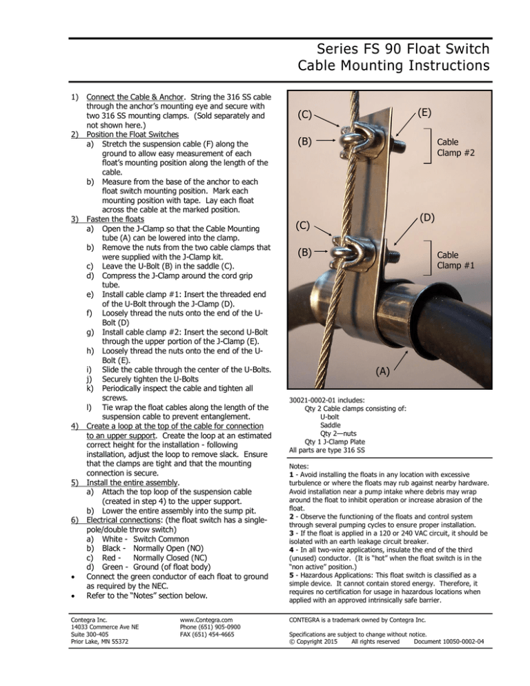
a) Open the J-Clamp so that the Cable Mounting
tube (A) can be lowered into the clamp.
b) Remove the nuts from the two cable clamps that
were supplied with the J-Clamp kit.
c) Leave the U-Bolt (B) in the saddle (C).
d) Compress the J-Clamp around the cord grip
tube.
e) Install cable clamp #1: Insert the threaded end
of the U-Bolt through the J-Clamp (D).
f) Loosely thread the nuts onto the end of the UBolt (D)
g) Install cable clamp #2: Insert the second U-Bolt
through the upper portion of the J-Clamp (E).
h) Loosely thread the nuts onto the end of the UBolt (E).
i) Slide the cable through the center of the U-Bolts.
j) Securely tighten the U-Bolts
k) Periodically inspect the cable and tighten all
screws.
l) Tie wrap the float cables along the length of the
suspension cable to prevent entanglement.
Create a loop at the top of the cable for connection
to an upper support. Create the loop at an estimated
correct height for the installation - following
installation, adjust the loop to remove slack. Ensure
that the clamps are tight and that the mounting
connection is secure.
Install the entire assembly.
a) Attach the top loop of the suspension cable
(created in step 4) to the upper support.
b) Lower the entire assembly into the sump pit.
Electrical connections: (the float switch has a singlepole/double throw switch)
a) White - Switch Common
b) Black - Normally Open (NO)
c) Red Normally Closed (NC)
d) Green - Ground (of float body)
Connect the green conductor of each float to ground
as required by the NEC.
Refer to the “Notes” section below.
Contegra Inc.
14033 Commerce Ave NE
Suite 300-405
Prior Lake, MN 55372
www.Contegra.com
Phone (651) 905-0900
FAX (651) 454-4665
(E)
(C)
(B)
Cable
Clamp #2
(D)
(C)
(B)
Cable
Clamp #1
(A)
30021-0002-01 includes:
Qty 2 Cable clamps consisting of:
U-bolt
Saddle
Qty 2—nuts
Qty 1 J-Clamp Plate
All parts are type 316 SS
Notes:
1 - Avoid installing the floats in any location with excessive
turbulence or where the floats may rub against nearby hardware.
Avoid installation near a pump intake where debris may wrap
around the float to inhibit operation or increase abrasion of the
float.
2 - Observe the functioning of the floats and control system
through several pumping cycles to ensure proper installation.
3 - If the float is applied in a 120 or 240 VAC circuit, it should be
isolated with an earth leakage circuit breaker.
4 - In all two-wire applications, insulate the end of the third
(unused) conductor. (It is “hot” when the float switch is in the
“non active” position.)
5 - Hazardous Applications: This float switch is classified as a
simple device. It cannot contain stored energy. Therefore, it
requires no certification for usage in hazardous locations when
applied with an approved intrinsically safe barrier.
CONTEGRA is a trademark owned by Contegra Inc.
Specifications are subject to change without notice.
© Copyright 2015
All rights reserved
Document 10050-0002-04


