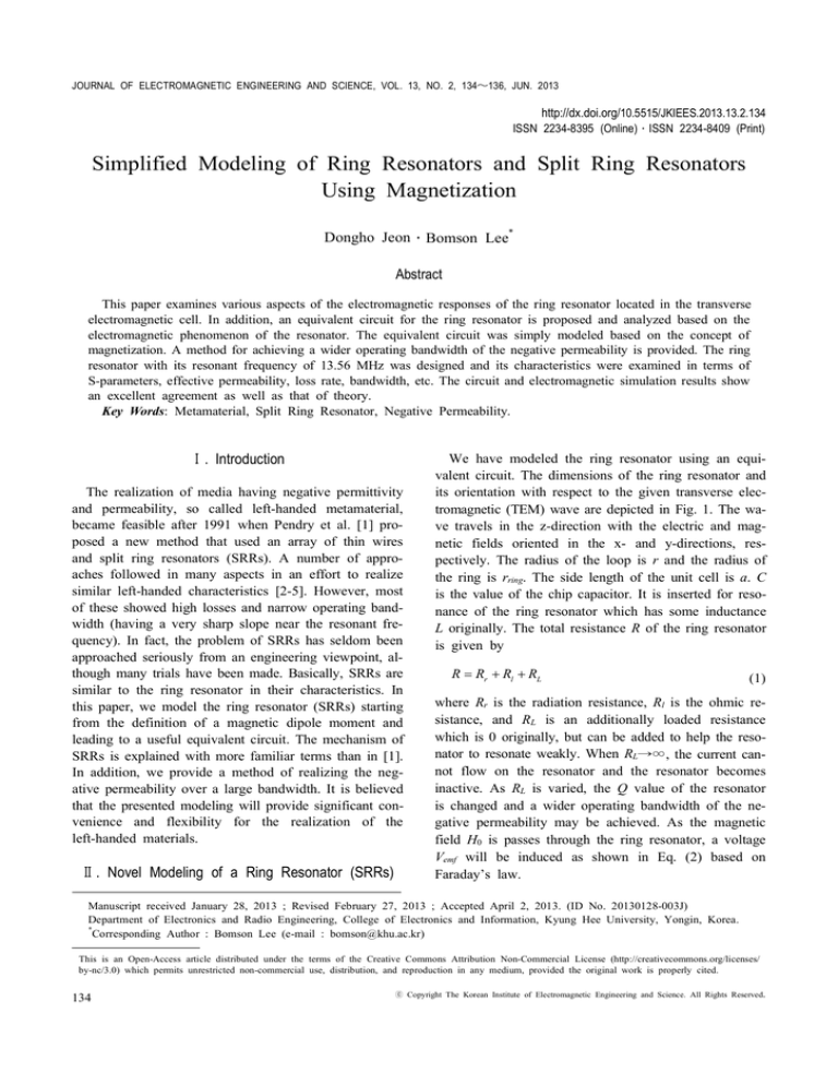
JOURNAL OF ELECTROMAGNETIC ENGINEERING AND SCIENCE, VOL. 13, NO. 2, 134~136, JUN. 2013
http://dx.doi.org/10.5515/JKIEES.2013.13.2.134
ISSN 2234-8395 (Online)․ISSN 2234-8409 (Print)
Simplified Modeling of Ring Resonators and Split Ring Resonators
Using Magnetization
Dongho Jeon․Bomson Lee*
Abstract
This paper examines various aspects of the electromagnetic responses of the ring resonator located in the transverse
electromagnetic cell. In addition, an equivalent circuit for the ring resonator is proposed and analyzed based on the
electromagnetic phenomenon of the resonator. The equivalent circuit was simply modeled based on the concept of
magnetization. A method for achieving a wider operating bandwidth of the negative permeability is provided. The ring
resonator with its resonant frequency of 13.56 MHz was designed and its characteristics were examined in terms of
S-parameters, effective permeability, loss rate, bandwidth, etc. The circuit and electromagnetic simulation results show
an excellent agreement as well as that of theory.
Key Words: Metamaterial, Split Ring Resonator, Negative Permeability.
Ⅰ. Introduction
The realization of media having negative permittivity
and permeability, so called left-handed metamaterial,
became feasible after 1991 when Pendry et al. [1] proposed a new method that used an array of thin wires
and split ring resonators (SRRs). A number of approaches followed in many aspects in an effort to realize
similar left-handed characteristics [2-5]. However, most
of these showed high losses and narrow operating bandwidth (having a very sharp slope near the resonant frequency). In fact, the problem of SRRs has seldom been
approached seriously from an engineering viewpoint, although many trials have been made. Basically, SRRs are
similar to the ring resonator in their characteristics. In
this paper, we model the ring resonator (SRRs) starting
from the definition of a magnetic dipole moment and
leading to a useful equivalent circuit. The mechanism of
SRRs is explained with more familiar terms than in [1].
In addition, we provide a method of realizing the negative permeability over a large bandwidth. It is believed
that the presented modeling will provide significant convenience and flexibility for the realization of the
left-handed materials.
Ⅱ. Novel Modeling of a Ring Resonator (SRRs)
We have modeled the ring resonator using an equivalent circuit. The dimensions of the ring resonator and
its orientation with respect to the given transverse electromagnetic (TEM) wave are depicted in Fig. 1. The wave travels in the z-direction with the electric and magnetic fields oriented in the x- and y-directions, respectively. The radius of the loop is r and the radius of
the ring is rring. The side length of the unit cell is a. C
is the value of the chip capacitor. It is inserted for resonance of the ring resonator which has some inductance
L originally. The total resistance R of the ring resonator
is given by
R = Rr + Rl + RL
(1)
where Rr is the radiation resistance, Rl is the ohmic resistance, and RL is an additionally loaded resistance
which is 0 originally, but can be added to help the resonator to resonate weakly. When RL→∞, the current cannot flow on the resonator and the resonator becomes
inactive. As RL is varied, the Q value of the resonator
is changed and a wider operating bandwidth of the negative permeability may be achieved. As the magnetic
field H0 is passes through the ring resonator, a voltage
Vemf will be induced as shown in Eq. (2) based on
Faraday’s law.
Manuscript received January 28, 2013 ; Revised February 27, 2013 ; Accepted April 2, 2013. (ID No. 20130128-003J)
Department of Electronics and Radio Engineering, College of Electronics and Information, Kyung Hee University, Yongin, Korea.
*
Corresponding Author : Bomson Lee (e-mail : bomson@khu.ac.kr)
This is an Open-Access article distributed under the terms of the Creative Commons Attribution Non-Commercial License (http://creativecommons.org/licenses/
by-nc/3.0) which permits unrestricted non-commercial use, distribution, and reproduction in any medium, provided the original work is properly cited.
134
ⓒ Copyright The Korean Institute of Electromagnetic Engineering and Science. All Rights Reserved.
JEON and LEE : SIMPLIFIED MODELING OF RING RESONATORS AND SPLIT RING RESONATORS USING MAGNETIZATION
vemf =
¶ ( m 0 H 0p r 2 )
¶t
= jw
¶t
¾¾¾
® Vemf = jwm0 H 0p r 2
(2)
Accordingly, the current I can be easily determined as
Eq. (3) simply by dividing Vemf with the resonator impedance Z(ω) (series sum of R, L, and C).
I (w ) =
Vemf
Z (w )
=
jwm0 H 0p r 2
[ A]
æ w w0 ö
R + jRQ ç - ÷
è w0 w ø
Zeq (w) = jw Leq d +
(3)
The magnetization M and the relative effective permeability can be obtained as (4) and (5), respectively.
jwm0 H0 (p r 2 )
m(w)
M (w) =
=ay = cm (w)H0 ay
Dv
é
æ w w0 öù 3
+
R
jRQ
a
ê
ç
÷ú
(4)
è w0 w øû
ë
2
m eff (w ) = 1 + c m (w ) = 1 -
jwm0 (p r
)
2 2
é
æ w w0 ö ù
a3 ê R + jRQ ç
- ÷ú
è w0 w ø û
ë
(5)
where ω is angular frequency, ω0 is the resonant frequ2
ency, m(w ) is magnetic dipole moment ( m = I (w )p r ay ),
Q is the value of Q factor written as Eq. (6), χm is
magnetic susceptibility, and μ0 is the permeability in
free space (μ0=4π×10—7[H/m]).
Q=
w0 L
R
(6)
The parameter L in Eq. (6) indicates the self-inductance of the proposed ring resonator. Now, we want to
devise an equivalent circuit for the structure in Fig. 1.
By multiplying the derived relative effective permeability with the geometrical factor (g) which is determined for the cross-sectional shape of a specific transmission line, we can obtain the effective inductance of
the transmission line.
Leff (w ) = m 0 m eff (w ) g [ H / m]
valent circuit depicted in Fig. 2. The equivalent circuit
consists of a right handed (RH) transmission line with
Leq·d, Ceq·d and a parallel G', C', L' resonator in the series branch. The RH transmission line may be alternatively represented by Zc and kd. The total series impedance of the equivalent circuit in Fig. 2 can be written as
(7)
For an instance, g for the parallel plate waveguide
transmission line with width W and height h is given by
h/W. Now, the series impedance of the unit cell including the ring resonator can be expressed as
1
[W]
æ w w0 ö
¢
¢
G + jw0C ç - ÷
è w0 w ø
(9)
The value of parameters G', C', L' in Eq. (9) can be
obtained as Eq. (10) by comparing the Eqs. (8) and (9).
G¢ =
a3
a3
1
¢
R
C
L, L¢ = 2
=
,
2
2
w0 C
(wm0p r ) gd
(wm0p r ) gd
(10)
Ⅲ. Simulation Results and Discussion
The ring resonator used in the electromagnetic (EM)
simulation is made of copper and is designed at 13.56
MHz. The unit cell size (a) is 12 cm (0.005λ0). The radius of the loop (r) and the ring (rring) are 5 cm and 1
mm, respectively. The ohmic resistance Rl is 0.058 Ω
and the radiation loss Rr is negligible (RL=0 Ω assumed). The value of capacitance for the resonance is
533 pF. Fig. 3(a) and (b) show the circuit (based on
Fig. 2) and EM-simulated magnitude and phase of the
S-parameters for the ring resonator when the TEM wave
propagates in the z-direction as depicted in Fig. 1. The
circuit based on Fig. 2 and the EM-simulated results
show excellent agreement. The extracted real and imaginary parts of the effective permeability based on the
S-parameter [6] and theory (4) are shown in Fig. 4(a)
and (b), respectively. The excellent agreement validates
this modeling. In Fig. 5(a), the real part of the effective
permeability is shown with respect to the Q values which can be controlled by varying the extra resistance RL.
For this case, the ring resonators have been designed to have the specific value for effective permeability (μeff =—1)
of 13.56 MHz (each case has different resonant frequencies).
Fig. 5(b) shows the loss rate of the ring resonator with different values of Q. The loss rate is defined as Eq. (11).
2
h L = 1 - S11 - S 21
2
(11)
Z (w) = jwLeff (w)d
= jwm0 gd +
1
[W]
é
æ w w0 ö ù
a
ê R + jw0 L ç - ÷ ú
2
è w0 w ø û
(wm0p r 2 ) gd ë
(8)
3
where d is the physical length of the transmission line
unit cell. A close examination of (8) leads to the equi-
Fig. 1. Structure of a ring resonator.
135
JOURNAL OF ELECTROMAGNETIC ENGINEERING AND SCIENCE, VOL. 13, NO. 2, JUN. 2013
Q (Q=26.8, RL=0.8 Ω). The widest bandwidth is only effective when the effective permeability is designed to
have the value of —1. The circuit and EM-simulated results are again in excellent agreement.
Ⅳ. Conclusion
Fig. 2. Equivalent circuit of ring resonator.
(a)
The effective permeability of a ring resonator (or SRR)
has been formulated based on the concept of magnetization. Its equivalent circuit has also been proposed and
analyzed with necessary comparisons. The circuit and EM
simulated results are in excellent agreement. The drawback of the narrow-banded SRRs can be significantly ameliorated based on the proposed modeling and formulations.
With this modeling, the problem of synthesizing the effective medium can be engineered more systematically.
(b)
Fig. 3. Simulated S-parameters: (a) magnitude, (b) phase. EM
=electromagnetic.
This work was supported by Mid-career Researcher Program through the National Research Foundation of Korea (NRF) grant funded by the Korea
government (No. 2012047938).
References
(a)
(b)
Fig. 4. Extracted effective permeability at 13.56 MHz: (a)
real, (b) imaginary. EM=electromagnetic.
(a)
(b)
Fig. 5. Circuit/electromagnetic (EM)-simulated μeff and ηl
with respect to RL. (a) Re[μeff](varing RL from 0.15
to 500 Ω), (b) Loss rate, ηl (varing RL from 0.15
to 500 Ω).
Each case shows that the highest loss rate is shown
at the resonant frequency, but loss rates are very low at
the operating frequency of 13.56 MHz (ηl is less than
2.5% for each case).
Comparison of Figs. 4(a) and 5(a) shows that the resonance occurs less sensitively as the value of Q is lowered by inserting extra resistance RL’s. Furthermore, the
widest operating bandwidth of the effective permeability
is achieved when the resonator has the specific value of
136
[1] J. B. Pendry, A. J. Holden, D. J. Robbins, and W. J.
Stewart, "Magnetism from conductors and enhanced
nonlinear phenomena," IEEE Transactions on Microwave Theory and Techniques, vol. 47, no. 11, pp.
2075-2084, Nov. 1999.
[2] S. M. Rudolph, C. Pfeiffer, and A. Grbic, "Design
and free-space measurements of broadband, low-loss
negative-permeability and negative-Index media," IEEE Transactions on Antennas and Propagation, vol.
59, no. 8, pp. 2989-2997, Aug. 2011.
[3] K. Zhang, Q. Wu, J. H. Fu, F. Y. Meng, and L. W.
Li, "Metamaterials with tunable negative permeability based on mie resonance," IEEE Transactions on
Magnetics, vol. 48, no. 11, pp. 4289-4292, Nov. 2012.
[4] C. Kim and B. Lee, "Analysis of magnetically coupled wireless power transmission for maximum efficiency," Journal of Electromagnetic Engineering and
Science, vol. 11, no. 3, pp. 156-160, Dec. 2011.
[5] H. Luo, X. Wang, Z. Liao, T. Wang, and R. Gong,
"Experimental investigation of R(ω), T(ω), and L
(ω) for multi-layer SRRs and wires metamaterial,"
Journal of Electromagnetic Engineering and Science,
vol. 10, no. 3, pp. 186-189, Sep. 2010.
[6] S. G. Mao, S. L. Chen, and C. W. Huang, "Effective
electromagnetic parameters of novel distributed lefthanded microstrip lines," IEEE Transactions on Microwave Theory and Techniques, vol. 53, no. 4, pp.
1515-1521, Apr. 2005.

