Datasheet - Plöger Sensor GmbH
advertisement

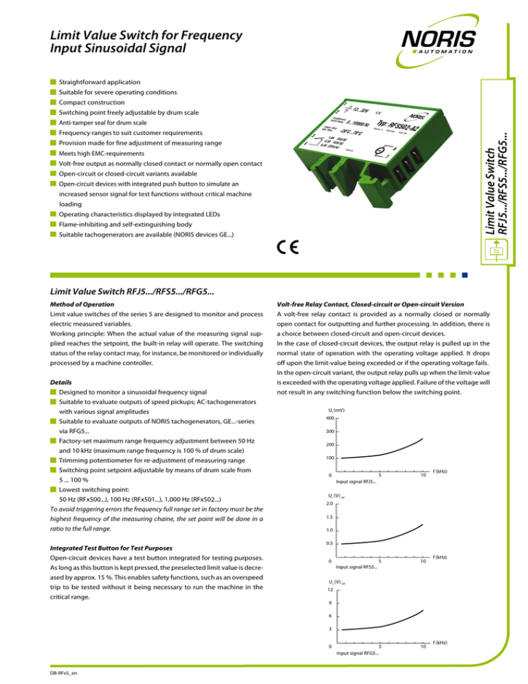
Limit Value Switch for Frequency Input Sinusoidal Signal Straightforward application Suitable for severe operating conditions 1 Schaltb Switch.Raereich: nge: Anti-tamper seal for drum scale Umgeb Amb. Tem. Temp: p: Frequency ranges to suit customer requirements Provision made for fine adjustment of measuring range Meets high EMC-requirements 12...32V 2 Switching point freely adjustable by drum scale 3 4 0...10000 -20°C...70° 1,0A 30 0,5A 60 V/DC V/ 0,2A 220V DC /AC TS256-424 C Hz Typ: RFS5 Revision: A ~ PN.031462 02-A2 Ta.02-1701 Limit Value Switch RFJ5.../RFS5.../RFG5... Compact construction 6 7 Volt-free output as normally closed contact or normally open contact Open-circuit or closed-circuit variants available Open-circuit devices with integrated push button to simulate an increased sensor signal for test functions without critical machine loading Operating characteristics displayed by integrated LEDs Flame-inhibiting and self-extinguishing body Suitable tachogenerators are available (NORIS devices GE...) Limit Value Switch RFJ5.../RFS5.../RFG5... Method of Operation Limit value switches of the series 5 are designed to monitor and process electric measured variables. Working principle: When the actual value of the measuring signal supplied reaches the setpoint, the built-in relay will operate. The switching status of the relay contact may, for instance, be monitored or individually processed by a machine controller. Details Designed to monitor a sinusoidal frequency signal Suitable to evaluate outputs of speed pickups; AC-tachogenerators with various signal amplitudes Suitable to evaluate outputs of NORIS tachogenerators, GE...-series via RFG5... Factory-set maximum range frequency adjustment between 50 Hz and 10 kHz (maximum range frequency is 100 % of drum scale) Trimming potentiometer for re-adjustment of measuring range Switching point setpoint adjustable by means of drum scale from 5 ... 100 % Lowest switching point: 50 Hz (RFx500...), 100 Hz (RFx501...), 1,000 Hz (RFx502...) To avoid triggering errors the frequency full range set in factory must be the highest frequency of the measuring chaine, the set point will be done in a ratio to the full range. Integrated Test Button for Test Purposes Open-circuit devices have a test button integrated for testing purposes. As long as this button is kept pressed, the preselected limit value is decreased by approx. 15 %. This enables safety functions, such as an overspeed trip to be tested without it being necessary to run the machine in the critical range. Volt-free Relay Contact, Closed-circuit or Open-circuit Version A volt-free relay contact is provided as a normally closed or normally open contact for outputting and further processing. In addition, there is a choice between closed-circuit and open-circuit devices. In the case of closed-circuit devices, the output relay is pulled up in the normal state of operation with the operating voltage applied. It drops off upon the limit-value being exceeded or if the operating voltage fails. In the open-circuit variant, the output relay pulls up when the limit-value is exceeded with the operating voltage applied. Failure of the voltage will not result in any switching function below the switching point. Ui (mV) 400 300 200 100 5 10 5 10 5 Input signal RFG5... 10 0 f (kHz) Input signal RFJ5... Ui (V) PP 2.0 1.5 1.0 0.5 0 f (kHz) Input signal RFS5... Ui (V) PP 12 9 6 3 0 DB-RFx5_en f (kHz) Dimensions, Connection, Diagram Technical Data UO=12 ... 32 VDC, UR=24 VDC Ripple < 20 % UO Power consumption Approx. 50 mA @ 24VDC Reverse voltage protection Integrated Overvoltage 2.5 times UR up to 2 ms Voltage drops 100 % up to 10 ms Connection contact DIN 46244: flat connector, gold-plated A6.3 x 0.8 Galvanic isolation Between input signal and supply voltage Input signal Sinusoidal signal, NORIS tachogenerator GE Input overloading RFJ5... up to 30 V, RFS5... and RFG5... up to 90 V Input resistance RFJ5... approx. 10 kΩ, RFS5... approx. 30 kΩ, RFG5... approx. 15 kΩ Output contact Volt-free NOC or NCC, closed circuit or open circuit 70 46 Supply voltage Anti-tamper seal LED green Max. switching capacity 30 W (1 A at 30 VDC; 0.5 A at 60 VDC); 40 W (0.2 A at 220 VAC) Switching point Adjustable on tamper-proof drum scale between 5 ... 100 % 17.5 Output Input Connection Series RFJ5.../RFS5.../RFG5... Other Mech. quantities Climatic test DIN IEC 60068-T2-30 Storage temperature -45 °C ... +85 °C Vibration resistance DIN IEC 60068-T2-6: 15 g increased strain, characteristic 2 (10 ... 100 Hz) G-channel TS32 to DIN EN 50035 Degree of protection DIN EN 60529: body IP20; terminals IP00 ESD IEC 61000-4-2: ± 8 kV Electromagnetic field IEC 61000-4-3: 10 V/m f=10 kHz ... 2.000 MHz, 80% AM @ 1 kHz 10 V/m f=900 ± 5 MHz, 50% AM @ 200 Hz 10 V/m f=1,800 MHz ± 5 MHz, 50% AM @ 200 Hz Burst IEC 61000-4-4: ±2 kV supply; ±1 kV sensor Surge IEC 61000-4-5: sym. ± 1 kV (Ri=2 Ω); asym. ± 2 kV (Ri=2 Ω) HF-interference IEC 61000-4-6: 3 VPP f=0.01 ... 100 MHz, 80% AM @ 1 kHz LF-interference IEC 60553: 3 VPP 0.05 ... 10 kHz Interference field intensity Basis CISPR 16-1, 16-2 reduced characteristic Case material Thermoplastic polyester, green Mounting Snap-fit on G-channel TS32 or top-hat channel TS35 Installation position Any Weight 55 g Reproducibility < ± 0.2 % Linearity of scale < ± 1.5 % Hysteresis Approx. 1.5 % Test button function Switching point lowered by approx. 15 % (only open-circuit devices) Accuracy class IEC 51-1: 1.5 % 15 Shock resistance (impact) DIN IEC 60068-T2-27: 300 m/s² with 18 ms dwell time Top-hat channel TS35 to DIN EN 50022 Connection NCC RFx5...-...1 1 + - 2 3 Temperature sensitivity < ± 0.1 % per 10 °K Approvals LED red 17 Environmental influences Operating temperature -20 °C ... +70 °C Voltage sensitivity < ± 0.1 % for 10 % change in supply voltage Reaction time f=50 Hz/0.25 s; f=100 Hz/0.2 s; f=1 kHz/0.1 s; f=10 kHz/50 ms Approvals CE Applied standards DIN EN 61000-6-2, DIN EN 61000-6-4, DIN EN 50155 Fire protection class V0 1 + - 3 FJ 5 01 – A2 (e. g. RFJ501-A2) 1 2 3 4 1 Device and series (Standard variants, other available on customer request) 2 Input signal FJ Frequency input for sinusoidal signal 100 mVPP ... 10 VPP FS Frequency input for sinusoidal signal 500 mVPP ... 30 VPP R Limit value switch FG Frequency input for sinusoidal signal 6 VPP ... 200 VPP 3 Type series 4 Input range fB/upper-range frequency fE/switching point fS 5 Type 5 00 fB=10 ... 100 Hz; fE=50 ... 100 Hz; fS=50 ... 100 Hz mit fS ≤ fE 01 fB=20 ... 1,000 Hz; fE=100 ... 1,000 Hz; fS=100 ... 1,000 Hz mit fS ≤ fE 02 fB=200 ... 10,000 Hz; fE=1,000 ... 10,000 Hz; fS=1,000 ... 10,000 Hz mit fS ≤ fE 6 ~ 4 R 7 Connection NOC RFx5...-...2 2 Type Code 6 ~ 4 7 Relais position and LED code 3/4 RFx5 ...-A1 5 3/4 RFx5 ...-A2 3/4 RFx5 ...-R1 3/4 RFx5 ...-R2 LED green LED red f < limit value x - - x x - f > switching point - x x - x x x = contact closed/LED lighting - = contact open/LED off o = LED flashing Standard Variants Frequency version NCC in closed circuit 00 01 02 RFx500-R1 RFx501-R1 RFx502-R1 5 Variant NOC in closed circuit RFx500-R2 RFx501-R2 RFx502-R2 R1 Output contact as NCC in closed circuit NCC in open circuit RFx500-A1 RFx501-A1 RFx502-A1 R2 Output contact as NOC in closed circuit NOC in open circuit RFx500-A2 RFx501-A2 RFx502-A2 A1 Output contact as NCC in open circuit A2 Output contact as NOC in open circuit x is to be replaced with range J, S or G of input signal Please state upper range frequency in case of order. NORIS Automation GmbH | Muggenhofer Strasse 95 | 90429 Nuremberg | Germany | Phone: +49 911 3201-220 | Fax: +49 911 3201-150 | sales@noris-group.com | www.noris-group.com valid from Rev. – DB-RFx5_en V02.00 - 06/2011 - Errors and omissions excepted.


