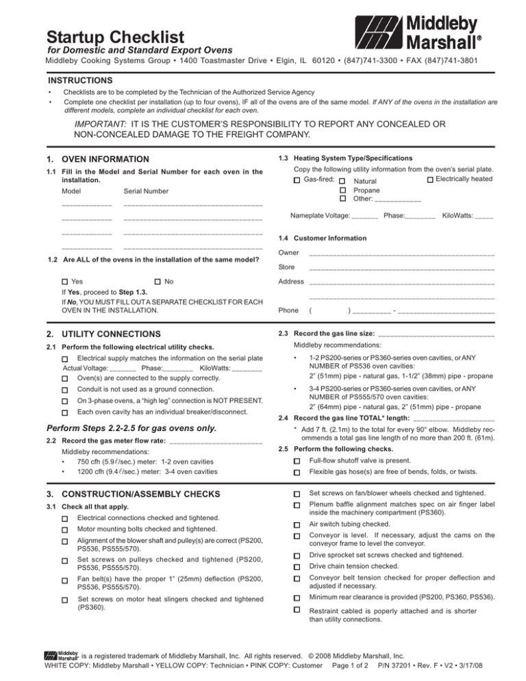
Startup Checklist
for Domestic and Standard Export Ovens
Middleby Cooking Systems Group • 1400 Toastmaster Drive • Elgin, IL 60120 • (847)741-3300 • FAX (847)741-3801
INSTRUCTIONS
•
•
Checklists are to be completed by the Technician of the Authorized Service Agency
Complete one checklist per installation (up to four ovens), IF all of the ovens are of the same model. If ANY of the ovens in the installation are
different models, complete an individual checklist for each oven.
IMPORTANT: IT IS THE CUSTOMER’S RESPONSIBILITY TO REPORT ANY CONCEALED OR
NON-CONCEALED DAMAGE TO THE FREIGHT COMPANY.
1.3 Heating System Type/Specifications
1. OVEN INFORMATION
1.1 Fill in the Model and Serial Number for each oven in the
installation.
Model
Serial Number
_____________
___________________________________
_____________
___________________________________
_____________
___________________________________
_____________
___________________________________
Copy the following utility information from the oven’s serial plate.
Electrically heated
Gas-fired:
Natural
Propane
Other: ____________
Nameplate Voltage: _______ Phase:________ KiloWatts: _____
1.4 Customer Information
Owner
_______________________________________________
Store
_______________________________________________
1.2 Are ALL of the ovens in the installation of the same model?
Yes
No
If Yes, proceed to Step 1.3.
If No, YOU MUST FILL OUT A SEPARATE CHECKLIST FOR EACH
OVEN IN THE INSTALLATION.
2. UTILITY CONNECTIONS
2.1 Perform the following electrical utility checks.
Electrical supply matches the information on the serial plate
Actual Voltage: _______ Phase:________ KiloWatts: ________
Oven(s) are connected to the supply correctly.
Conduit is not used as a ground connection.
On 3-phase ovens, a “high leg” connection is NOT PRESENT.
Each oven cavity has an individual breaker/disconnect.
Address _______________________________________________
_______________________________________________
Phone
(
) __________ - _________________________
2.3 Record the gas line size: ______________________________
Middleby recommendations:
•
1-2 PS200-series or PS360-series oven cavities, or ANY
NUMBER of PS536 oven cavities:
2” (51mm) pipe - natural gas, 1-1/2” (38mm) pipe - propane
•
3-4 PS200-series or PS360-series oven cavities, or ANY
NUMBER of PS555/570 oven cavities:
2” (64mm) pipe - natural gas, 2” (51mm) pipe - propane
2.4 Record the gas line TOTAL* length: _____________________
Perform Steps 2.2-2.5 for gas ovens only.
2.2 Record the gas meter flow rate: ________________________
Middleby recommendations:
•
750 cfh (5.9l/sec.) meter: 1-2 oven cavities
•
1200 cfh (9.4 l/sec.) meter: 3-4 oven cavities
* Add 7 ft. (2.1m) to the total for every 90° elbow. Middleby recommends a total gas line length of no more than 200 ft. (61m).
2.5 Perform the following checks.
Full-flow shutoff valve is present.
Flexible gas hose(s) are free of bends, folds, or twists.
3. CONSTRUCTION/ASSEMBLY CHECKS
Set screws on fan/blower wheels checked and tightened.
3.1 Check all that apply.
Plenum baffle alignment matches spec on air finger label
inside the machinery compartment (PS360).
Electrical connections checked and tightened.
Motor mounting bolts checked and tightened.
Alignment of the blower shaft and pulley(s) are correct (PS200,
PS536, PS555/570).
Set screws on pulleys checked and tightened (PS200,
PS536, PS555/570).
Air switch tubing checked.
Conveyor is level. If necessary, adjust the cams on the
conveyor frame to level the conveyor.
Drive sprocket set screws checked and tightened.
Drive chain tension checked.
Fan belt(s) have the proper 1” (25mm) deflection (PS200,
PS536, PS555/570).
Conveyor belt tension checked for proper deflection and
adjusted if necessary.
Set screws on motor heat slingers checked and tightened
(PS360).
Minimum rear clearance is provided (PS200, PS360, PS536).
Restraint cabled is poperly attached and is shorter
than utility connections.
is a registered trademark of Middleby Marshall, Inc. All rights reserved. © 2008 Middleby Marshall, Inc.
WHITE COPY: Middleby Marshall • YELLOW COPY: Technician • PINK COPY: Customer Page 1 of 2 P/N 37201 • Rev. F • V2 • 3/17/08
4. GAS SYSTEM CHECKS
4.1 Perform the following gas system checks.
Leak detector/soap solution test performed on all gas line
joints and unions. Connections tightened if necessary.
Natural Gas
Current reading across the pilot flame sensor measures
at least 2.0µA with the oven(s) on low flame.
Gas line is dedicated for ovens only.
Gas pressures fall into the following acceptable ranges:
Incoming Static Gas Pressure: _______________w.c.
Inlet
pressure
Regulated
pressure
Pilot
pressure
Natural
gas
6-12” W.C.
14.9-29.9 mbar
3½” W.C.
8.7 mbar
3½-4” W.C.
8.7-10.0mbar
Propane
11-14” W.C.
27.4-34.9 mbar
10” W.C.
24.9mbar
8-10” W.C.
19.9-24.9mbar
Propane [LP] Gas
Incoming Dynamic Gas Pressure: _______________w.c.
Actual Manifold Gas Pressure: _______________w.c.
Modulation Valve set and functioning properly?
5. OPERATION AND VENTIALATION CHECK CHECKS
5.1 Perform the following tests.
Cooling fan(s) operate and draw air inward.
Blower wheels/fans are oriented properly and rotate in the
correct direction.
For ovens that have had the conveyor direction reversed, the
conveyor belt has also been reversed.
Air fingers correctly assembled and installed.
What type of hood is present? ______________________
Is there sufficient make up air?
5.2 Run a test product through the oven to perform the following
checks.
For ovens that have had the conveyor direction reversed, the
air finger configuration has also been reversed.
Oven maintains the set point temperature.
Ventilation hood is present (REQUIRED for all gas ovens consult local codes for electric ovens).
Time the test product from the time the trailing edge enters
the oven to the time the trailing edge exits the oven. The
speed controller accurately displays this baking time.
6. CUSTOMER CHECKS
6.1 Perform the following.
Service agency sticker (if available) placed on oven.
Customer has been instructed in operating the oven(s) under
normal conditions.
Customer has been instructed in cleaning the oven(s),
including conveyor removal and air finger disassembly.
Customer has been provided with the
Owner's Operating Manual.
Customer has been given the opportunity to ask any questions
about operatiing, cleanind, or maintaining the oven(s).
SIGNING BELOW INDICATES APPROVAL OF THE INSTALLATION AND OPERATION OF THE OVEN(S). AFTER
THIS SECTION HAS BEEN SIGNED BY BOTH THE TECHNICIAN AND THE CUSTOMER, THE OVEN(S) MAY BE
OPERATED BY THE CUSTOMER.
Technician
Customer
____________________________________
Signature
____/____/____
Date
______________________________________
____/____/____
Signature
Date
Service Agency _______________________________________
Address
_________________________________________
_________________________________________
_________________________________________
Phone
(
) __________ - ____________________
is a registered trademark of Middleby Marshall, Inc. All rights reserved. © 2008 Middleby Marshall, Inc.
WHITE COPY: Middleby Marshall • YELLOW COPY: Technician • PINK COPY: Customer Page 2 of 2 P/N 37201 • Rev. F • V2 • 3/17/08


