Booster Element Relay for Hot Water
F2476 January 2015
31VBER
Installation Instructions
Description
The 31VBER Booster Element Relay for Hot Water suits hot water
heating systems that have a booster element and thermostat. The
31VBER’s boost relay de-energises when the water reaches the
temperature governed by the thermostat. The product has a pushbutton
switch and a neon indicator that indicates when the booster element is
operating.
PRESS FOR
BOOSTER ELEMENT
Application Restriction
WARNING
HOT WATER
Solar Hot Water Systems
Use the 31VBER only for the purpose for which it is designed.
Schneider Electric does not endorse the use of the product to modify or
interfere with the normal operation of any solar hot water system.
Wiring Instructions
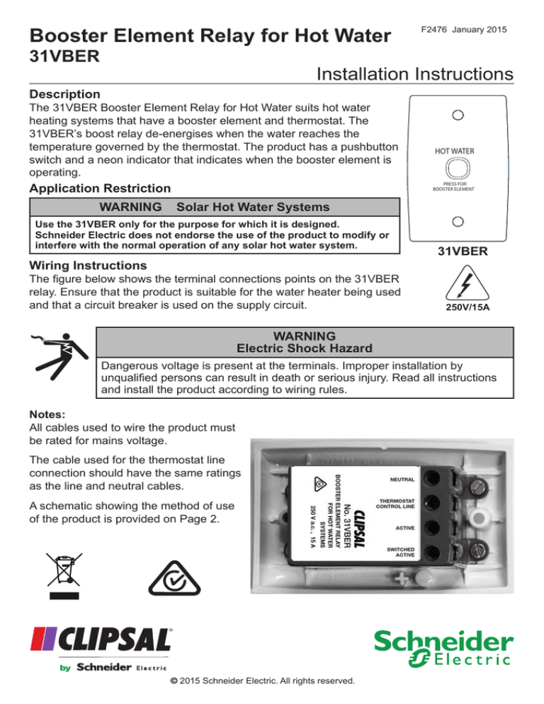
The figure below shows the terminal connections points on the 31VBER
relay. Ensure that the product is suitable for the water heater being used
and that a circuit breaker is used on the supply circuit.
31VBER
250V/15A
WARNING
Electric Shock Hazard
Dangerous voltage is present at the terminals. Improper installation by
unqualified persons can result in death or serious injury. Read all instructions
and install the product according to wiring rules.
Notes:
All cables used to wire the product must
be rated for mains voltage.
The cable used for the thermostat line
connection should have the same ratings
as the line and neutral cables.
A schematic showing the method of use
of the product is provided on Page 2.
®
© 2015 Schneider Electric. All rights reserved.
31VBER Booster Element Relay for Hot Water
Application
Connect the product as
shown in the wiring diagram
to the right.
Ensure that the control line
de-energises the relay when
the thermostat senses the
set temperature.
Installation Instructions
31VBER Booster Relay
Active
L
N
E
Active
Switched
Active
Thermostat
Control Line
Load
This connection must
be on the load side of
the thermostat
Neutral
Heater with
Thermostat
Specifications
The 31VBER must never be operated outside of an approved fixed location.
Specification
Value/Description
Supply voltage
240 Va.c., nominal
Supply frequency
50 Hz
Relay rating
15 A, for resistive load.
Wired Connections
Active line input (Active) 250V mains
Neutral line (Neutral)
Output (Switched Active)
Control (Thermostat Control Line)
Wired connections use screw terminals.
Switch type
Pushbutton with neon indicator
Dimensions
Length: 115 mm; Height: 73 mm
mounting centres: 84 mm apart
Depth
Plate: 16 mm; Button: 4.5 mm.
Operating ambient temperature
5°-45° C, switch may feel warm to the touch when active.
Operating humidity
10-90% RH, non-condensing
Warranty Period
2 years against manufacturing defects
Technical Support
If you need technical assistance or warranty information, contact your local Schneider Electric
sales office or customer care.
Customer care email: http://www.schneider-electric.com select Support and your country
Schneider Electric (Australia) Pty Ltd
33-37 Port Wakefield Road
Gepps Cross, SA 5094
clipsal.com
Contact us: clipsal.com/feedback
© 2015 Schneider Electric. All rights reserved.
Schneider Electric (Australia) Pty Ltd reserves the right to change specifications, modify designs and discontinue items
without incurring obligation. Every effort is made to ensure that descriptions, specifications and other information in this
document are correct. However, no warranty is given in respect thereof and the company shall not be liable for any error
therein.
Trademarks are owned by Schneider Electric Industries SA or its affiliated companies.


