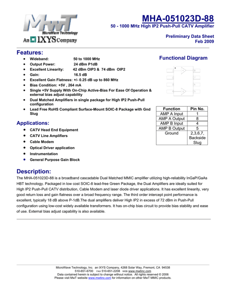
MHA-051023D-88
50 - 1000 MHz High IP2 Push-Pull CATV Amplifier
Preliminary Data Sheet
Feb 2009
Features:
•
•
•
•
•
•
•
•
•
Wideband:
50 to 1000 MHz
Output Power:
24 dBm P1dB
Excellent Linearity:
42 dBm OIP3 & 74 dBm OIP2
Gain:
16.5 dB
Excellent Gain Flatness: +/- 0.25 dB up to 860 MHz
Bias Condition: +5V , 264 mA
Single +5V Supply With On-Chip Active-Bias For Ease Of Operation &
external bias adjust capability
Dual Matched Amplifiers in single package for High IP2 Push-Pull
configuration
Lead Free RoHS Compliant Surface-Mount SOIC-8 Package with Gnd
Slug
Applications:
• CATV Head End Equipment
• CATV Line Amplifiers
• Cable Modem
• Optical Driver application
• Instrumentation
• General Purpose Gain Block
Functional Diagram
Function
AMP A Input
AMP A Output
AMP B Input
AMP B Output
Ground
Pin No.
1
8
4
5
2,3,6,7,
Backside
Slug
Description:
The MHA-051023D-88 is a broadband cascadable Dual Matched MMIC amplifier utilizing high-reliability InGaP/GaAs
HBT technology. Packaged in low cost SOIC-8 lead-free Green Package, the Dual Amplifiers are ideally suited for
High IP2 Push-Pull CATV distribution, Cable Modem and laser diode driver applications. It has excellent linearity, very
good return loss and gain flatness over a broad frequency range. The third order intercept point performance is
excellent, typically 18 dB above P-1dB.The dual amplifiers deliver High IP2 in excess of 72 dBm in Push-Pull
configuration using low-cost widely available transformers. It has on-chip bias circuit to provide bias stability and ease
of use. External bias adjust capability is also available.
MicroWave Technology, Inc. an IXYS Company, 4268 Solar Way, Fremont, CA 94538
510-651-6700 FAX 510-651-2208 WEB www.mwtinc.com
Data contained herein is subject to change without notice. All rights reserved © 2006
Please visit MwT website www.mwtinc.com for information on other MwT MMIC products.
MHA-051023D-88
50 - 1000 MHz High IP2 Push-Pull CATV Amplifier
Preliminary Data Sheet
Feb 2009
Electrical Specifications:
Parameter
Frequency Range
Gain
Gain Flatness
@ Vcc=+5.0V, Icc=264mA, Ta=25 °C Z0=75 ohm (1)
Units
Typical
MHz
50-1000
dB
16.5
50 MHz to 860 MHz
+/-dB
0.25
dB
dB
Input Return Loss
Output Return Loss
Output P-1dB
dBm
Output IP3
@ 8 dBm/tone, 1 MHz separation
Output IP2
@ 8 dBm/tone
dBm
dBm
Noise Figure
Operating Bias Conditions: Vcc
Icc
dB
V
mA
14
20
23.7
24.0
24.2
23.9
23.8
42
43
42.5
41
40.5
76
75
76
85
72
68
5.3
+5
264
50 MHz
250 MHz
500 MHz
860 MHz
1000 MHz
50 MHz
250 MHz
500 MHz
860 MHz
1000 MHz
499/553 MHz, Meas @ 54 MHz
811/865 MHz, Meas @ 54 MHz
439/853 MHz, Meas @ 414 MHz
427/433 MHz, Meas @ 860 MHz
327/533 MHz, Meas @ 860 MHz
227/633 MHz, Meas @ 860 MHz
Combined Pair
(1) All Data is measured on Evaluation PCB in 75-ohm Push-Pull configuration optimized for wideband (50-1000 MHz) performance referenced to
RF connectors
Absolute Maximum Ratings:
SYMBOL
PARAMETERS
UNITS
ABSOLUTE MAXIMUM
Vcc
Collector Voltage
V
5.5
Icc
Collector Current
mA
300
Pdiss
DC Power Dissipation
W
TBD
Pin max
RF Input Power
dBm
TBD
Toper
Operating Case/Lead Temperature Range
ºC
- 40 to + 85
Tch
Channel Temperature
ºC
150
Tstg
Storage Temperature
ºC
-60 to +150
*Operation of this device above any one of these parameters may cause permanent damage.
MicroWave Technology, Inc. an IXYS Company, 4268 Solar Way, Fremont, CA 94538
510-651-6700 FAX 510-651-2208 WEB www.mwtinc.com
Data contained herein is subject to change without notice. All rights reserved © 2006
Please visit MwT website www.mwtinc.com for information on other MwT MMIC products.
MHA-051023D-88
50 - 1000 MHz High IP2 Push-Pull CATV Amplifier
Preliminary Data Sheet
Feb 2009
Typical RF Performance:
Vcc=5V, Icc=264mA, Ta=25 °C Z0 = 75 Ohm, Push-Pull Evaluation PCB
Return Loss versus Frequency
Gain versus Frequency
Input
-5
Return Loss (dB)
19
Gain (dB)
Output
0
20
18
17
16
15
-10
-15
-20
-25
-30
-35
-40
14
-45
0.1 0.2 0.3 0.4 0.5 0.6 0.7 0.8 0.9
1
0
0.1 0.2 0.3 0.4 0.5 0.6 0.7 0.8 0.9
Frequency (GHz)
Frequency (GHz)
Isolation versus Frequency
Noise Figure versus Frequency
0
9
-5
8
Noise Figure (dB)
isolation (dB)
0
-10
-15
-20
-25
-30
7
6
5
4
3
0
0.1 0.2 0.3 0.4 0.5 0.6 0.7 0.8 0.9
1
0
0.1
0.2 0.3
Frequency (GHz)
0.4 0.5 0.6
0.7 0.8
0.9
1
0.9
1
Frequency (GHz)
Output IP3 versus Frequency
P-1dB versus Frequency
25
44
24
42
OIP3 (dBm)
P-1dB (dBm)
1
23
22
21
40
38
36
20
34
0
0.1
0.2
0.3
0.4
0.5 0.6
0.7
Frequency (GHz)
0.8
0.9
1
0
0.1
0.2
0.3
0.4
0.5 0.6
0.7
Frequency (GHz)
MicroWave Technology, Inc. an IXYS Company, 4268 Solar Way, Fremont, CA 94538
510-651-6700 FAX 510-651-2208 WEB www.mwtinc.com
Data contained herein is subject to change without notice. All rights reserved © 2006
Please visit MwT website www.mwtinc.com for information on other MwT MMIC products.
0.8
MHA-051023D-88
50 - 1000 MHz High IP2 Push-Pull CATV Amplifier
Preliminary Data Sheet
Feb 2009
75- ohm Push-Pull Application Circuit Schematic
C11
C=1 uF
VCC1
C9
C=1000 pF
C3
C=100 pF
R3
R=6.98 kOhm
1
C1
C=.01 uF
T1
A
C7
C=33 pF
8
C5
C=0.01 uF
R1
R=7.5 Ohm
T2
RFIN
R2
R=7.5 Ohm
C2
C=.01 uF
C4
C=100 pF
L1
L=680 nH
4
5
RFOUT
B
R4
R=6.98 kOhm
C6
C=0.01 uF
L2
L=680 nH
C8
C=33 pF
C10
C=1000 pF
C12
C=1 uF
VCC2
NOTES:
1) R3, R4 are optimized for setting the desired bias current
2) R1, C3 and R2,C4 are designed to compensate for transformer insertion loss roll-off and optimize overall gain
flatness.
3) Bias is applied from each side using RF choke at each amplifier RF output
4) DC blocking capacitors are required at amplifier input & output.
5) The package backside slug must be soldered to PCB gnd vias for RF/DC grounding and optimum thermal
impedance. See PCB layout for details.
MicroWave Technology, Inc. an IXYS Company, 4268 Solar Way, Fremont, CA 94538
510-651-6700 FAX 510-651-2208 WEB www.mwtinc.com
Data contained herein is subject to change without notice. All rights reserved © 2006
Please visit MwT website www.mwtinc.com for information on other MwT MMIC products.
MHA-051023D-88
50 - 1000 MHz High IP2 Push-Pull CATV Amplifier
Preliminary Data Sheet
Feb 2009
75-ohm Push-Pull Amplifier Evaluation Board Layout & BOM
NOTES:
1) PCB is 4-layer stack. Material: VT-461 Er=3.66 Top Layer to 1st Gnd Layer Thickness: 28 mil with total 1 oz
plated Cu. Total Board Thickness: 65 mil.
2) RF Input/Output interface is designed for 75-ohm BNC End-launch connectors.
3) Evaluation Board measured with transformer MABA-007327. Alternatively other commercial transformers like
MABACT0059, ETC1-1-13 and ADTL1-18-75 should give equivalent performance.
PCB 03-50-117 Application Circuit BOM
MHA-051023D-88
Ref #
Part No.
R1,R2
R3,R4
C1,C2
C3,C4
C7,C8
C9,C10
C5,C6
C11,C12
L1,L2
U1
T1,T2
P1,P2
PCB
J1,J2
RK73B1ETTP7R5J (0402)
RK73H1ETTP6981F (0402)
0402YC103KAT2A
04025A101JAT2A
04025A330JAT2A
04025C102KAT2A
06035C103KAT2A
0603YD105KAT2A
0603LS-681XJLB
MHA-051023D-88
MABA-007327-CT1A40
TSM-105-01-S-SV
03-50-117 REV_
112622 BNC END LAUNCH
Value
Vendor
7.5 ohm
6.98K Ohm
0.01uF
100pF
33 pF
1000 pF
0.01 uF
1 uF
680 nH
SOIC-8 PKG
BALUN
DC STRIP
KOA
KOA
AVX
AVX
AVX
AVX
AVX
AVX
COILCRAFT
MWT
MACOM
SAMTEC
MWT
AMPHENOL
75 ohm BNC JACK
MicroWave Technology, Inc. an IXYS Company, 4268 Solar Way, Fremont, CA 94538
510-651-6700 FAX 510-651-2208 WEB www.mwtinc.com
Data contained herein is subject to change without notice. All rights reserved © 2006
Please visit MwT website www.mwtinc.com for information on other MwT MMIC products.
MHA-051023D-88
50 - 1000 MHz High IP2 Push-Pull CATV Amplifier
Preliminary Data Sheet
Feb 2009
Mechanical Information:
Package is RoHs-compliant lead free Green Package: 150mil Body SOIC-8 with ground slug
θ
NOTE
1. PACKAGE BODY SIZES EXCLUDE MOLD FLASH AND
GATE BURRS
2. DIMENSION L IS MEASURED IN GAGE PLANE
3. TOLERANCE 0.10 mm UNLESS OTHERWISE SPECIFIED
4. CONTROLLING DIMENSION IS MILLIMETER. CONVERTED
INCH DIMENSIONS ARE NOT NECESSARILY EXACT.
5. FOLLOWED FROM JEDEC MS-012
6. THERMAL SLUG DIMENSION : 75mils X 100mils
SYMBOLS
A
A1
A2
B
C
D
E
e
H
L
y
θ
DIMENSIONS IN MILLIMETERS
MIN
1.45
0.00
−−−
0.33
0.19
4.80
3.80
−−−
5.80
0.40
−−−
0°
NOM
1.50
−−−
1.45
−−−
−−−
−−−
−−−
1.27
−−−
−−−
−−−
−−−
MAX
1.55
0.15
−−−
0.51
0.25
5.00
4.00
−−−
6.20
1.27
0.10
8°
DIMENSIONS IN INCHES
MIN
0.057
0.000
−−−
0.013
0.007
0.189
0.150
−−−
0.228
0.016
−−−
0°
NOM
0.059
−−−
0.057
−−−
−−−
−−−
−−−
0.050
−−−
−−−
−−−
−−−
MAX
0.061
0.006
−−−
0.020
0.010
0.197
0.157
−−−
0.244
0.050
0.004
8°
MicroWave Technology, Inc. an IXYS Company, 4268 Solar Way, Fremont, CA 94538
510-651-6700 FAX 510-651-2208 WEB www.mwtinc.com
Data contained herein is subject to change without notice. All rights reserved © 2006
Please visit MwT website www.mwtinc.com for information on other MwT MMIC products.


