ILLUMINATION
LUXEON 3030 2D and
LUXEON 3030 HV
Assembly and Handling Information
Introduction
This application brief addresses the recommended assembly and handling
guidelines for LUXEON 3030 2D and LUXEON 3030 HV emitters. These emitters
deliver high efficacy and quality of light for distributed light source applications
in a compact 3.0mm x 3.0mm package. Proper assembly, handling, and thermal
management, as outlined in this application brief, ensure high optical output and
reliability of these emitters.
Scope
The assembly and handling guidelines in this application brief apply to the following
LUXEON products:
PRODUCTS
LUXEON 3030 2D
LUXEON 3030 HV
In the remainder of this document the term LUXEON emitter refers to any product in
the LUXEON series listed above.
AB207 LUXEON 3030 2D and LUXEON 3030 HV Application Brief ©2016 Lumileds Holding B.V. All rights reserved.
Table of Contents
Introduction . . . . . . . . . . . . . . . . . . . . . . . . . . . . . . . . . . . . . . . . . . . . . . . . . . . . . . . . . . . . . . . . . . . . . . . . . . 1
Scope . . . . . . . . . . . . . . . . . . . . . . . . . . . . . . . . . . . . . . . . . . . . . . . . . . . . . . . . . . . . . . . . . . . . . . . . . . . . . . . . 1
1.Component . . . . . . . . . . . . . . . . . . . . . . . . . . . . . . . . . . . . . . . . . . . . . . . . . . . . . . . . . . . . . . . . . . . . . . . . 3
1.1 Description . . . . . . . . . . . . . . . . . . . . . . . . . . . . . . . . . . . . . . . . . . . . . . . . . . . . . . . . . . . . . . . . . . . . . . . . . 3
1.2 Optical Center . . . . . . . . . . . . . . . . . . . . . . . . . . . . . . . . . . . . . . . . . . . . . . . . . . . . . . . . . . . . . . . . . . . . . . . 3
1.3 Handling Precautions . . . . . . . . . . . . . . . . . . . . . . . . . . . . . . . . . . . . . . . . . . . . . . . . . . . . . . . . . . . . . . . . 3
1.4 Cleaning . . . . . . . . . . . . . . . . . . . . . . . . . . . . . . . . . . . . . . . . . . . . . . . . . . . . . . . . . . . . . . . . . . . . . . . . . . . . 3
1.5 Electrical Isolation . . . . . . . . . . . . . . . . . . . . . . . . . . . . . . . . . . . . . . . . . . . . . . . . . . . . . . . . . . . . . . . . . . . 4
1.6 Mechanical Files . . . . . . . . . . . . . . . . . . . . . . . . . . . . . . . . . . . . . . . . . . . . . . . . . . . . . . . . . . . . . . . . . . . . . 4
2. PCB Design Guidelines for the LUXEON Emitter . . . . . . . . . . . . . . . . . . . . . . . . . . . . . . . . . . . . . . . . . 4
2.1 PCB Footprint and Land Pattern . . . . . . . . . . . . . . . . . . . . . . . . . . . . . . . . . . . . . . . . . . . . . . . . . . . . . . . 4
2.2 Surface Finishing . . . . . . . . . . . . . . . . . . . . . . . . . . . . . . . . . . . . . . . . . . . . . . . . . . . . . . . . . . . . . . . . . . . . 4
2.3 Minimum Spacing . . . . . . . . . . . . . . . . . . . . . . . . . . . . . . . . . . . . . . . . . . . . . . . . . . . . . . . . . . . . . . . . . . . 4
3. Thermal Management . . . . . . . . . . . . . . . . . . . . . . . . . . . . . . . . . . . . . . . . . . . . . . . . . . . . . . . . . . . . . . . 5
4. Thermal Measurement Guidelines . . . . . . . . . . . . . . . . . . . . . . . . . . . . . . . . . . . . . . . . . . . . . . . . . . . . 7
5. Assembly Process Guidelines . . . . . . . . . . . . . . . . . . . . . . . . . . . . . . . . . . . . . . . . . . . . . . . . . . . . . . . . . 8
5.1 Stencil Design . . . . . . . . . . . . . . . . . . . . . . . . . . . . . . . . . . . . . . . . . . . . . . . . . . . . . . . . . . . . . . . . . . . . . . . 8
5.2 Solder Paste . . . . . . . . . . . . . . . . . . . . . . . . . . . . . . . . . . . . . . . . . . . . . . . . . . . . . . . . . . . . . . . . . . . . . . . . 8
5.3 Solder Reflow Profile . . . . . . . . . . . . . . . . . . . . . . . . . . . . . . . . . . . . . . . . . . . . . . . . . . . . . . . . . . . . . . . . . 8
5.4 Pick and Place . . . . . . . . . . . . . . . . . . . . . . . . . . . . . . . . . . . . . . . . . . . . . . . . . . . . . . . . . . . . . . . . . . . . . . . 8
5.5 Electrostatic Discharge Protection . . . . . . . . . . . . . . . . . . . . . . . . . . . . . . . . . . . . . . . . . . . . . . . . . . . . . 9
5.6 JEDEC Moisture Sensitivity . . . . . . . . . . . . . . . . . . . . . . . . . . . . . . . . . . . . . . . . . . . . . . . . . . . . . . . . . . . . 9
6. Packaging Considerations — Chemical Compatibility . . . . . . . . . . . . . . . . . . . . . . . . . . . . . . . . . . . . 9
AB207 LUXEON 3030 2D and LUXEON 3030 HV Application Brief 20160303 ©2016 Lumileds Holding B.V. All rights reserved.
2
1.Component
1.1 Description
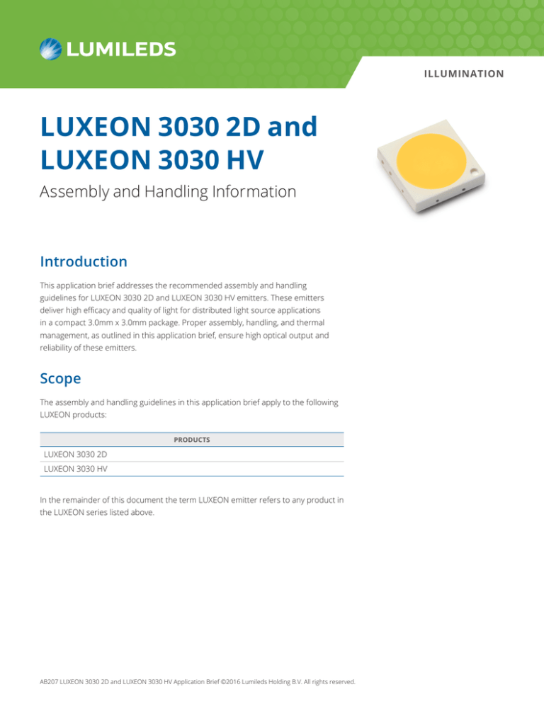
The LUXEON emitter (Figure 1) is an EMC (epoxy molding compound) molded, no-lead, surface mount package consisting
of an anode and a cathode. A small circle on the corner of the package marks the cathode side of the emitter package.
Majority of the heat is being dissipated through the larger pad (cathode). The LUXEON emitter does not include any
transient voltage suppressor (TVS) chip to protect the emitter against electrostatic discharges (ESD) Appropriate
precautions should therefore be taken when handling this device (see Section 5.5). The inspectable solder joint feature
(Figure 1) to check the presence of solder fillet for quality monitoring is not used.
1.2 Optical Center
The optical center coincides with the mechanical center of the LUXEON emitter. Optical rayset data for the LUXEON
emitter are available at lumileds.com.
1.3 Handling Precautions
The LUXEON emitter is designed to maximize light output and reliability. However, improper handling of the device may
damage the silicone encapsulation and affect the overall performance and reliability. In order to minimize the risk of
damage to the silicone encapsulation during handling, the LUXEON emitter should only be picked up from the side of the
package (Figure 2).
1.4 Cleaning
The LUXEON emitter should not be exposed to dust and debris. Excessive dust and debris may cause a drastic decrease
in optical output. In the event that a LUXEON emitter requires cleaning, first try a gentle swabbing using a lint-free swab.
If needed, a lint-free swab and isopropyl alcohol (IPA) can be used to gently remove dirt from the silicone coating. Do not
use other solvents as they may adversely react with the package of the LUXEON emitter. For more information regarding
chemical compatibility, see Section 6.
Figure 1. Package rendering of the LUXEON 3030 2D emitter.
Figure 2. Correct handling (left) and incorrect handling (right) of LUXEON emitters.
AB207 LUXEON 3030 2D and LUXEON 3030 HV Application Brief 20160303 ©2016 Lumileds Holding B.V. All rights reserved.
3
1.5 Electrical Isolation
The LUXEON emitter contains two electrode pads on the package. It is important to keep sufficient distance between the
LUXEON emitter package and any other objects or neighboring LUXEON emitters to prevent any accidental shorts.
In order to avoid any electrical shocks, flashover and/or damage to the LUXEON emitter, each design needs to comply with
the appropriate standards of safety and isolation distances, known as clearance and creepage distances, respectively (e.g.
IEC60950, clause 2.10.4).
1.6 Mechanical Files
Mechanical drawings for the LUXEON emitter are available at lumileds.com.
2. PCB Design Guidelines for the LUXEON Emitter
The LUXEON emitter is designed to be soldered onto a Printed Circuit Board (PCB). To ensure optimal operation, the PCB
should be designed to minimize the overall thermal resistance between the LED package and the heat sink.
2.1 PCB Footprint and Land Pattern
The recommended PCB footprint design for the LUXEON emitter is shown in Figure 3. In order to ensure proper heat
dissipation from the emitter electrodes to the PCB, it is best to extend the top copper layer of the PCB beyond the
perimeter of the LUXEON emitter by at least 4mm (see Section 3).
2.2 Surface Finishing
Lumileds recommends using a high temperature organic solderability preservative (OSP) or electroless nickel immersion
gold (ENIG) plating on the exposed copper pads.
2.3 Minimum Spacing
Lumileds recommends a minimum edge to edge spacing between LUXEON emitters of 0.5mm. Placing multiple LUXEON
emitters too close to each other may adversely impact the ability of the PCB to dissipate the heat from the emitters.
AB207 LUXEON 3030 2D and LUXEON 3030 HV Application Brief 20160303 ©2016 Lumileds Holding B.V. All rights reserved.
4
0.58
0.48
0.05
0.69
2.30
2.10
0.13
1.15
2.20
2.30
Solder mask
Stencil
Top copper
Package geometric center
1.33
1.53
Figure 3. Recommended PCB footprint design for the LUXEON emitter (top). In order to ensure proper heat
dissipation from the package electrodes to the PCB, it is best to extend the top copper layer of the PCB several
millimeters beyond the package of the LUXEON emitter. See Section 3 for more information on the copper layout.
All dimensions are in mm. Bottom picture shows the actual FR4 PCB footprint layout.
3. Thermal Management
The overall thermal resistance between a LUXEON emitter and the heat sink is strongly affected by the design and material
of the PCB on which the emitter is soldered. Metal Core PCBs have been historically used in the LED industry for their low
thermal resistance and rigidity. However, MCPCBs may not always offer the most economical solution. Multi-layer epoxy
FR4 PCBs are commonly used in the electronics industry and can, if properly designed, yield an appropriate low-cost
solution for various LED applications.
Lumileds investigated the thermal performance of LUXEON emitters on a 1.0mm thick FR4 PCB with a top copper plating
of 35μm (single sided copper layer PCB). In order to quantify the impact of the top copper metallization design layout on
the overall thermal resistance between junction and heat sink, two designs with varying copper trace layout around the
anode and cathode were evaluated as shown in Table 1. The two designs are:
a. A – Minimum top copper corresponds to copper trace which extends beyond the outline of the LUXEON
emitter package by 0.25mm which corresponds to half of the minimum recommended package to package
spacing of 0.5mm. This configuration is representative of worst case condition for application where multiple
LEDs are placed in close proximity to each other.
b. B – Maximize top copper around the cathode as much as possible. This is the ideal layout for FR4 PCB since the
primary heat flow of the LUXEON emitter is through the cathode pad as described in section 1.1.
As general guidelines, increasing the top copper thickness and increasing the copper area around the cathode will reduce
the FR4 board thermal resistance. Adding a bottom copper layer to the FR4 (double sided copper clad PCB) does not
reduce the FR4 thermal resistance since the FR4 material itself is a poor thermal conductor.
AB207 LUXEON 3030 2D and LUXEON 3030 HV Application Brief 20160303 ©2016 Lumileds Holding B.V. All rights reserved.
5
Table 1. Typical thermal resistance values for FR4 PCBs with varying top copper trace pattern (solid red area). Design B yields
the lowest board thermal resistance.
Design
Typical Rθj- bottom PCB
[K/W]
Typical Rθj-s
[K/W]
74
18
32
12
A (mimimum copper pattern, 0.25mm around package outline)
B (maximize copper around cathode pad)
AB207 LUXEON 3030 2D and LUXEON 3030 HV Application Brief 20160303 ©2016 Lumileds Holding B.V. All rights reserved.
6
Figure 4. The recommended temperature measurement point Ts is located on the cathode copper layer of the PCB,
closest to the package. The picture above shows where to place the welding tip of the TC wire prior to dispensing
any thermal conductive epoxy to secure the TC wire.
Tip of TC
wire secured
with epoxy
Figure 5. Photo showing actual placement of TC wire secured with thermal conductive epoxy.
The thermal epoxy volume should be kept to minimum as shown.
4. Thermal Measurement Guidelines
The typical thermal resistance Rθ
j-case
between the junction and the solder pads of the LUXEON emitter is provided in the
datasheet. With this information, the junction temperature Tj can be determined according to the following equation:
T =T
j
In this equation T
case
thermal pad
+ Rθ
j-thermal pad
•P
electrical
is the temperature at the bottom of the solder pads of the LUXEON emitter and Pelectrical is the electrical
power going into the emitter. In typical applications it may be difficult, though, to measure the temperature Tcase directly.
Therefore, a practical way to determine the junction temperature of the LUXEON emitter is by measuring the temperature
Ts of a predetermined sensor pad on the PCB with a thermocouple.
The recommended location of the sensor pad is right next to the cathode of the LUXEON emitter on the PCB, as shown
in Figure 4 and Figure 5. To ensure accurate reading, the thermocouple (TC) tip must make direct contact to the copper
of the PCB onto which the LUXEON emitter cathode pad is soldered, i.e. any solder mask or other masking layer must
be first removed before mounting the thermocouple onto the PCB. The tip of the TC wire where two dissimilar metals
are welded should be placed as close as possible to the LUXEON emitter package on the exposed cathode copper
layer as shown in Figure 4. The thermal resistance Rθ between the sensor pad and the LUXEON emitter junction was
j-s
experimentally determined on FR4 PCBs for the two different designs (see Table 1). The junction temperature can then
be calculated as follows:
T = T + Rθ • P
j
s
j-s
electrical
It is recommended to secure the tip of TC wire to the exposed copper area with a good thermal conductive epoxy such as
Artic Silver™ thermal adhesive. Note that the Artic Silver™ epoxy is not formulated to conduct electricity. During dispensing
of epoxy, avoid flooding the TC wire with too much epoxy but sufficient enough to secure the TC wire for measurement.
Putting more epoxy than needed may change the thermal behavior of the surrounding area.
AB207 LUXEON 3030 2D and LUXEON 3030 HV Application Brief 20160303 ©2016 Lumileds Holding B.V. All rights reserved.
7
5. Assembly Process Guidelines
5.1 Stencil Design
The recommended solder stencil thickness is 125μm or 5mils.
5.2 Solder Paste
Lumileds recommends lead-free solder for the LUXEON emitter such as SAC 305 solder paste from Alpha Metals (SAC305CVP390-M20 type 3). However, since application environments vary widely, Lumileds recommends that customers perform
their own solder paste evaluation in order to ensure it is suitable for the targeted application.
5.3 Solder Reflow Profile
The LUXEON emitter is compatible with standard surface-mount and lead-free reflow technologies. This greatly simplifies
the manufacturing process by eliminating the need for adhesives and epoxies. The reflow step itself is the most critical
step in the reflow soldering process and occurs when the boards move through the oven and the solder paste melts,
forming the solder joints. To form good solder joints, the time and temperature profile throughout the reflow process
must be well maintained.
A temperature profile consists of three primary phases:
1. Preheat: the board enters the reflow oven and is warmed up to a temperature lower than the melting point of the
solder alloy.
2. Reflow: the board is heated to a peak temperature above the melting point of the solder, but below the temperature
that would damage the components or the board.
3. Cool down: the board is cooled down rapidly, allowing the solder to freeze, before the board exits the oven.
As a point of reference, the melting temperature for SAC 305 is 217°C, and the minimum peak reflow temperature is 235°C.
5.4 Pick and Place
The LUXEON emitter is packaged and shipped in tape-and-reel which is compatible with standard automated pick-andplace equipment to ensure the best placement accuracy. Note that pick and place nozzles are customer specific and are
typically machined to fit specific pick and place tools. Lumileds advises customer to take the following general pick and
place guidelines into account:
a. The nozzle tip should be clean and free of any particles since they may interact with the top surface of the
silicone encapsulation of the LUXEON emitter package.
b. During setup and the first initial production runs, it is a good practice to inspect the top surface of the
LUXEON emitters under a microscope to ensure that the emitters are not accidentally damaged by the pick
and place nozzle.
AB207 LUXEON 3030 2D and LUXEON 3030 HV Application Brief 20160303 ©2016 Lumileds Holding B.V. All rights reserved.
8
5.5 Electrostatic Discharge Protection
The LUXEON emitter does not include any transient voltage suppressor (TVS) chip to protect against electrostatic discharges
(ESD). Therefore, Lumileds recommends observing the following precautions when handling the LUXEON emitter:
During manual handling always use a conductive wrist band or ankle straps when positioned on a grounded
conductive mat.
All equipment, machinery, work tables, and storage racks that may get in contact with the LUXEON emitter should be
properly grounded.
Use an ion blower to neutralize the static discharge that may build up on the surface and lens of the plastic housing of
the LUXEON emitter during storage and handling.
LUXEON emitters which are damaged by ESD may not light up at low currents and/or may exhibit abnormal performance
characteristics such as a high reverse leakage current, and a low forward voltage (leaky diode). It is also important to take
note that ESD can also cause latent failure, i.e. failure or symptoms as described above may not show up immediately but
until after use. Hence continuous ESD protection is needed during assembly.
5.6 JEDEC Moisture Sensitivity
LUXEON 3030 2D MSL (JEDEC moisture sensitivity level) is rated as level 3. Proper storage, handling and/or baking must be
adhered to prevent damage to the LUXEON emitter during reflow.
Table 2.
3
Soak Requirements
Standard
Floor Life
MSL Level
Time
Conditions
Time
Conditions
168 Hours
≤30°C / 60% RH
(Relative Humidity)
192 +5 / -0 Hours
30°C / 60% RH
Table 3. Storage and baking conditions. Note that if any of the temperature, relative humidity, humidity indicator card or the
period is not met, baking is required. For more information, see IPC/JEDEC J-STD-033C
Operation
Packing Bag Status
Temperature
Relative
Humidity (RH)
Humidity
Indicator Card
Period
Storage
As received
≤30°C (non-condensing
atmospheric
environment)
≤90%
n/a
Within 1 year of
shipment date
Storage
After opening bag
≤30°C
≤60%
If 10% color spot is
no longer blue
168 Hours
Baking (drying)
n/a
60 ±5°C
≤5%
n/a
≥24 Hours
6. Packaging Considerations — Chemical Compatibility
The LUXEON emitter package contains a silicone overcoat to protect the LED chip and extract the maximum amount of
light. As with most silicones used in LED optics, care must be taken to prevent any incompatible chemicals from directly or
indirectly reacting with the silicone.
The silicone overcoat used in the LUXEON emitter is gas permeable. Consequently, oxygen and volatile organic compound
(VOC) gas molecules can diffuse into the silicone overcoat. VOCs may originate from adhesives, solder fluxes, conformal
coating materials, potting materials and even some of the inks that are used to print the PCBs.
AB207 LUXEON 3030 2D and LUXEON 3030 HV Application Brief 20160303 ©2016 Lumileds Holding B.V. All rights reserved.
9
Some VOCs and chemicals react with silicone and produce discoloration and surface damage. Other VOCs do not
chemically react with the silicone material directly but diffuse into the silicone and oxidize during the presence of heat or
light. Regardless of the physical mechanism, both cases may affect the total LED light output. Since silicone permeability
increases with temperature, more VOCs may diffuse into and/or evaporate out from the silicone.
Careful consideration must be given to whether LUXEON emitters are enclosed in an “air tight” environment or not. In an
“air tight” environment, some VOCs that were introduced during assembly may permeate and remain in the silicone. Under
heat and “blue” light, VOCs captured inside the silicone may partially oxidize and create a silicone discoloration, particularly
on the surface of the LED where the flux energy is the highest. In an air rich or “open” air environment, VOCs have a
chance to leave the area (driven by the normal air flow). Transferring the devices which were discolored in the enclosed
environment back to “open” air may allow the oxidized VOCs to diffuse out of the silicone and may restore the original
optical properties of the LED.
Determining suitable threshold limits for the presence of VOCs is very difficult since these limits depend on the type of
enclosure used to house the LEDs and the operating temperatures. Also, some VOCs can photo-degrade over time.
Table 4 provides a list of commonly used chemicals that should be avoided as they may react with the silicone material.
Note that Lumileds does not warrant that this list is exhaustive since it is impossible to determine all chemicals that may
affect LED performance.
The chemicals in Table 4 are typically not directly used in the final products that are built around LUXEON emitters.
However, some of these chemicals may be used in intermediate manufacturing steps (e.g. cleaning agents).
Consequently, trace amounts of these chemicals may remain on (sub) components, such heat sinks. Lumileds, therefore,
recommends the following precautions when designing your application:
–– When designing secondary lenses to be used over an LED, provide a sufficiently large air-pocket and allow for
“ventilation” of this air away from the immediate vicinity of the LED.
–– Use mechanical means of attaching lenses and circuit boards as much as possible. When using adhesives, potting
compounds and coatings, carefully analyze its material composition and do thorough testing of the entire fixture
under High Temperature over Life (HTOL) conditions.
AB207 LUXEON 3030 2D and LUXEON 3030 HV Application Brief 20160303 ©2016 Lumileds Holding B.V. All rights reserved.
10
Table 4. List of commonly used chemicals that will damage the silicone of the LUXEON emitter. Avoid using any of these
chemicals in the housing that contains the LED package.
Chemical Name
Normally used as
Hydrochloric acid
acid
Sulfuric acid
acid
Nitric acid
acid
Acetic acid
acid
Sodium hydroxide
alkali
Potassium hydroxide
alkali
Ammonia
alkali
MEK (Methyl Ethyl Ketone)
solvent
MIBK (Methyl Isobutyl Ketone)
solvent
Toluene
solvent
Xylene
solvent
Benzene
solvent
Gasoline
solvent
Mineral spirits
solvent
Dichloromethane
solvent
Tetracholorometane
solvent
Castor oil
oil
Lard
oil
Linseed oil
oil
Petroleum
oil
Silicone oil
oil
Halogenated hydrocarbons
(containing F, Cl, Br elements)
misc
Rosin flux
solder flux
Acrylic tape
adhesive
RoHS
No. E352519
COMPLIANT
AB207 LUXEON 3030 2D and LUXEON 3030 HV Application Brief 20160303 ©2016 Lumileds Holding B.V. All rights reserved.
11
About Lumileds
Lumileds is the global leader in light engine technology. The company develops, manufactures and distributes groundbreaking
LEDs and automotive lighting products that shatter the status quo and help customers gain and maintain a competitive edge.
With a rich history of industry “firsts,” Lumileds is uniquely positioned to deliver lighting advancements well into the future by
maintaining an unwavering focus on quality, innovation and reliability.
To learn more about our portfolio of light engines, visit lumileds.com.
©2016 Lumileds Holding B.V. All rights reserved.
LUXEON is a registered trademark of the Lumileds Holding B.V.
in the United States and other countries.
lumileds.com
AB207 LUXEON 3030 2D and LUXEON 3030 HV
Application Brief 20160303
Neither Lumileds Holding B.V. nor its affiliates shall be liable for any kind of loss of data or any
other damages, direct, indirect or consequential, resulting from the use of the provided
information and data. Although Lumileds Holding B.V. and/or its affiliates have attempted to
provide the most accurate information and data, the materials and services information and data
are provided “as is,” and neither Lumileds Holding B.V. nor its affiliates warrants or guarantees
the contents and correctness of the provided information and data. Lumileds Holding B.V. and its
affiliates reserve the right to make changes without notice. You as user agree to this disclaimer
and user agreement with the download or use of the provided materials, information and data.

