Three-Phase PWM Rectifier Employing Two Single
advertisement

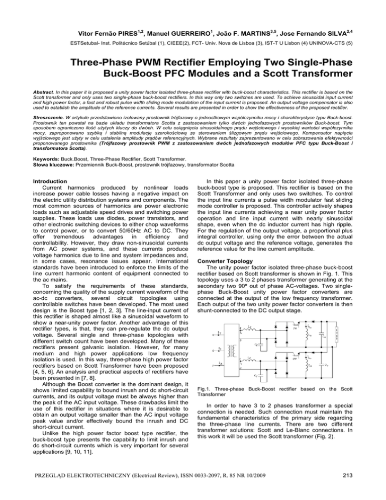
Vitor Fernão PIRES1,2, Manuel GUERREIRO1, João F. MARTINS3,5, Jose Fernando SILVA2,4 ESTSetubal- Inst. Politécnico Setúbal (1), CIEEE(2), FCT- Univ. Nova de Lisboa (3), IST-T U Lisbon (4) UNINOVA-CTS (5) Three-Phase PWM Rectifier Employing Two Single-Phase Buck-Boost PFC Modules and a Scott Transformer Abstract. In this paper it is proposed a unity power factor isolated three-phase rectifier with buck-boost characteristics. This rectifier is based on the Scott transformer and only uses two single-phase buck-boost rectifiers. In this way only two switches are used. To achieve sinusoidal input current and high power factor, a fast and robust pulse width sliding mode modulation of the input current is proposed. An output voltage compensator is also used to establish the amplitude of the reference currents. Several results are presented in order to show the effectiveness of the proposed rectifier. Streszczenie. W artykule przedstawiono izolowany prostownik trójfazowy o jednostkowym współczynniku mocy i charakterystyce typu Buck-boost. Prostownik ten powstał na bazie układu transformatora Scotta z zastosowaniem tylko dwóch jednofazowych prostowników Buck-boost. Tym sposobem ograniczono ilość użytych kluczy do dwóch. W celu osiągnięcia sinusoidalnego prądu wejściowego i wysokiej wartości współczynnika mocy, zaproponowano szybką i stabilną modulację szerokościową ze sterowaniem ślizgowym prądu wejściowego. Kompensator napięcia wyjściowego jest użyty w celu ustalenia amplitudy prądów referencyjnych. Wybrane rezultaty zaprezentowano w celu zobrazowania efektywności proponowanego prostownika (Trójfazowy prostownik PWM z zastosowaniem dwóch jednofazowych modułów PFC typu Buck-Boost i transformatora Scotta). Keywords: Buck.Boost, Three-Phase Rectifier, Scott Transformer. Słowa kluczowe: Przemiennik Buck-Boost, prostownik trójfazowy, transformator Scotta Introduction Current harmonics produced by nonlinear loads increase power cable losses having a negative impact on the electric utility distribution systems and components. The most common sources of harmonics are power electronic loads such as adjustable speed drives and switching power supplies. These loads use diodes, power transistors, and other electronic switching devices to either chop waveforms to control power, or to convert 50/60Hz AC to DC. They offer tremendous advantages in efficiency and controllability. However, they draw non-sinusoidal currents from AC power systems, and these currents produce voltage harmonics due to line and system impedances and, in some cases, resonance issues appear. International standards have been introduced to enforce the limits of the line current harmonic content of equipment connected to the ac mains. To satisfy the requirements of these standards, concerning the quality of the supply current waveform of the ac-dc converters, several circuit topologies using controllable switches have been developed. The most used design is the Boost type [1, 2, 3]. The line-input current of this rectifier is shaped almost like a sinusoidal waveform to show a near-unity power factor. Another advantage of this rectifier types, is that, they can pre-regulate the dc output voltage. Several single and three-phase topologies with different switch count have been developed. Many of these rectifiers present galvanic isolation. However, for many medium and high power applications low frequency isolation is used. In this way, three-phase high power factor rectifiers based on Scott Transformer have been proposed [4, 5, 6]. An analysis and practical aspects of rectifiers have been presented in [7, 8]. Although the Boost converter is the dominant design, it shows limited capability to bound inrush and dc short-circuit currents, and its output voltage must be always higher than the peak of the AC input voltage. These drawbacks limit the use of this rectifier in situations where it is desirable to obtain an output voltage smaller than the AC input voltage peak value and/or effectively bound the inrush and DC short-circuit current. Unlike the high power factor boost type rectifier, the buck-boost type presents the capability to limit inrush and dc short-circuit currents which is very important for several applications [9, 10, 11]. In this paper a unity power factor isolated three-phase buck-boost type is proposed. This rectifier is based on the Scott Transformer and only uses two switches. To control the input line currents a pulse width modulator fast sliding mode controller is proposed. This controller actively shapes the input line currents achieving a near unity power factor operation and line input current with nearly sinusoidal shape, even when the dc inductor current has high ripple. For the regulation of the output voltage, a proportional plus integral controller, using only the error between the actual dc output voltage and the reference voltage, generates the reference value for the line current amplitude. Converter Topology The unity power factor isolated three-phase buck-boost rectifier based on Scott transformer is shown in Fig. 1. This topology uses a 3 to 2 phases transformer generating at the secondary two 90º out of phase AC-voltages. Two singlephase Buck-Boost unity power factor converters are connected at the output of the low frequency transformer. Each output of the two unity power factor converters is then shunt-connected to the DC output stage. Fig.1. Three-phase Buck-Boost rectifier based on the Scott Transformer In order to have 3 to 2 phases transformer a special connection is needed. Such connection must maintain the fundamental characteristics of the primary side regarding the three-phase line currents. There are two different transformer solutions: Scott and Le-Blanc connections. In this work it will be used the Scott transformer (Fig. 2). PRZEGLĄD ELEKTROTECHNICZNY (Electrical Review), ISSN 0033-2097, R. 85 NR 10/2009 213 To control the input line current of each Buck-Boost module, a PWM sliding mode control technique will be used. Considering the is current as the controlled output, the input-output linearization of the state-space model (1) gives the state-space equations in the controllability canonical form (4): ⎤ ⎡ θ ⎥ ⎢ ⎥ ⎢ ⎥ ω 1 d ⎡i s ⎤ ⎢ R f ⎢ ⎥ = ⎢ − L θ − L C i s + L Vs max cos(ωt ) −⎥ dt ⎣θ ⎦ ⎢ ⎥ f f f f ⎥ ⎢ α α 1 2 ⎥ ⎢ i Lo1 − i Lo 2 − ⎥ ⎢ L f Cf L f Cf ⎦ ⎣ Fig.2. Connection and phasor diagram of the Scott Transformer The output voltages of the Scott transformer are 90º shifted and equal in magnitude. For the theoretical study of this isolated rectifier only the secondary circuitry will be taken into account. In this way, the input voltages of the rectifier are two ideal AC voltages. Rectifier Model Considering one set of input filter, bridge rectifier plus buck-boost converter and applying Kirchhoff laws, the dynamic behaviour of each rectifier can be described by the following state equations: ⎧ ⎪ ⎪ ⎪ ⎪ ⎪⎪ ⎨ ⎪ ⎪ ⎪ ⎪ ⎪ ⎪⎩ (1) Rf dis = − dt Lf dvC f 1 = dt Cf di Lo dt = dVC o = dt α Lo is − 1 1 vC f + vs Lf Lf is − vC f − 1− α Co α Cf i Lo γ (1 − α ) iLo − Lo VC o 1 Vo Ro Co where: (2) (3) α ⎧⎪ 1 , switch ON and vC f ≥ v Lo = ⎨ ⎪⎩ 0 , switch OFF or vC f < v Lo γ ⎧⎪ 1 , iLo > 0 = ⎨ ⎪⎩ 0 , iLo ≤ 0 This model will be used to define the system controllers. Control Strategy The system dynamics of each Buck-Boost module can be divided into fast motion (input line current) and slow motion (output voltage). In this way, owing to the separate dynamics of the input line current and of the output voltage, a cascade control structure is used. The reference for the inner current loop is a sinusoidal waveform whose amplitude is modulated by the external voltage controller as can be seen in Fig. 3. (4) where: θ= (5) vs − R f is − vC f Lf Analysing the obtained state space equations (4) and (5), it is possible to verify that the input line current has a strong relative degree of two [12]. In this way, a suitable sliding surface to ensure the robustness of the closed loop system [13] can be obtained. Equation (6) shows the correspondent defined sliding surface. ( S ei s , eθ (6) ) = ( isref − is ) + k ( θ ref −θ ) k is a parameter related to the time constant of the desired first order response of input source current iS (k>0). From (4) and (6), the sliding surface (7) is rewritten as: ( S ei s , eθ ) = ( isref ) − is + k (7) (v k Lf − s disref dt − − R f is − vC f ) The control strategy must guarantee that the system trajectory moves towards and stays on the sliding surface S ei s , eθ = 0 from any initial condition. In order to ( ) ensure this, the following stability condition must be obtained. ( (8) S ei s , eθ ) S ( ei , eθ ) < • s 0 The stability condition (8) is ensured by the following simple energy flow considerations: • If S ei , eθ < 0 then isref > is , hence is must s ( ) increase. In this way choose α = 1 ( Fig.3. Control strategy block diagram 214 ) • If S ei s , eθ > 0 then isref < is , hence is must increase. In this way choose α = 0 The fixed frequency current controller is obtained using an S-R flip-flop as presented in Figure 4. Since the current loop presents a much faster dynamics than the voltage loop, then its closed-loop transfer function can be simplified and represented as a current controlled delayed current source. In this way, the following transfer function of the current loop is obtained: PRZEGLĄD ELEKTROTECHNICZNY (Electrical Review), ISSN 0033-2097, R. 85 NR 10/2009 with the proposed control system provides almost sinusoidal input currents and near unity power factor. Fig. 11 shows an experimental result of the rectifier output voltage for a three-phase voltage swell. From this figure it is possible to confirm that the experimental transient response of the controller achieves a fast enough voltage regulation. Fig.4. Constant frequency operation of the current controller I = I ref (9) KI (1 + sTd ) Where K I represents the gain and Td the time delay of the source response. Considering that the rectifier is conservative (input power equals the output power) the K I gain can be obtained from: KI ≈ (10) Fig.5. Simulation result of the input voltage and line current Vs max 2 Vo The parameters of the voltage control block can now be obtained. From Fig. 3 it is possible to verify that the rectifier output voltage is controlled by changing the amplitude of the input current. In this way, from the closed loop transfer function, equations (11) and (12) give the parameters of the PI controller, using 2 2 for the required damping factor of the resulting 2ª order system. (11) KI ≈ (12) KI ≈ Vs max 2 Vo Fig.6. Simulation result of the rectifier phase line currents Vs max 2 Vo Results Several results are presented in order to verify the study of this system. The simulation results have been obtained using the program Matlab-Simulink/Power System Blockset. For the AC side of the rectifiers a filter with 1 mH inductor and 5 μF capacitor was used. For the output of the buckboost an inductor of 50 μΗ and a 470 μF capacitor were used. Fig. 5 presents a simulation result of the input voltage and line current. From this result it is possible to verify that the rectifier provides almost sinusoidal input current and high power factor. Fig. 6 shows the simulation result of the rectifier phase line currents. As can be seen these currents are nearly sinusoidal and 90º out of phase. Fig. 7 shows the simulation result of the transformer input line currents and voltage in phase R. From this result it is possible to observe the three-phase currents. They are balanced and enable high power factor. Fig. 8 and 9 show simulation results of the input line currents and rectifier output voltage for a three-phase voltage sag. As can be seen by this result, the PI controller achieves a sufficiently fast voltage regulation. Some experimental results are also presented. Fig. 10 shows an experimental result of the input voltage and line current in one of the rectifiers. The total harmonic distortion (THD) of the input line currents is 3.3%. So, from this experimental result it is possible to confirm that this rectifier Fig.7. Simulation result of the transformer input line currents and voltage in phase R Fig.8. Simulation result of the input line currents PRZEGLĄD ELEKTROTECHNICZNY (Electrical Review), ISSN 0033-2097, R. 85 NR 10/2009 215 REFERENCES [1] [2] [3] [4] Fig.9. Simulation result of the rectifier output voltage [5] [6] [7] [8] [9] Fig.10. Experimental result of the input voltage and line current [10] [11] [12] [13] Fig.11. Experimental result of the rectifier output voltage Conclusions In this paper a unity power factor isolated three-phase rectifier with buck-boost characteristics has been proposed. It is based on the Scott transformer and only uses two active switches. The rectifier is able to generate symmetrical currents in the line. To control the rectifier currents a fast and robust pulse with modulation sliding mode approach was used. A PI compensator was used to regulate the output voltage. This compensator determines the amplitude of the reference currents. Several results were presented to show the performances of each singlephase rectifier and the performances of the three-phase PWM rectifier. 216 M o h a n N . , U n d e l a n d T . M . , F e r r a r o R . J., Sinusoidal line current rectification with a 100kHz B-SIT step up converter, IEEE Power Electronics Specialists Conference, (1984), 92-98 B o y s J . T . , G r e e n A . W . , Current-forced single-phase reversible rectifier, IEE Proceedings-B, 136 (1989), No. 5, 237-242 S a l m o n J . C ., Techniques for Minimizing the Input Current Distortion of Current-Controlled Single-Phase Boost Rectifiers, IEEE Transactions on Power Electronics, 8 (1993), No. 4, 509520 R u f f e r A . , A n d r i a n i r i n a C h . - B ., A symmetrical 3 phase 2-switch PFC-power supply for variable output voltage, EPE'95: European Conference on Power Electronics and Aplications, (1995) B a d i n A . A . , B a r b i I ., Simplified Control Technique for Three-Phase Rectifier PFC Based on the Scott Transformer, IEEE ISIE 2006, (2006), 931-936 B a d i n A . A . , B a r b i I . , Unity Power Factor Isolated ThreePhase Rectifier With Split DC-Bus Based on the Scott Transformer, IEEE Transactions on Power Electronics, 23 (2008), No. 3, 1278-1287 M i l l e r S . K . T . , B a r b i I . , Practical aspects of the unity power factor isolated three-phase rectifier based on the Scott transformer, Applied Power Electronics Conference-APEC, (2005), 621-627 M i l l e r S . K . T . , B a r b i I . , Unity power factor isolated three-phase rectifier," 6th INDUSCON – Internacional Conference on Industrial Applications, (2004) F u n a b i k i S . , T o i t a N . , M e c h i A ., A Single-Phase PWM ac to dc Converter with a Step-up/down voltage and Sinusoidal Source Current, IEEE IAS Annual Meeting Record, (1991), 1017-1022 P i r e s V . F . , S i l v a J . F . , Half Bridge Single Phase BuckBoost Type ac-dc Converter with Sliding Mode Control of the Input Source Current, IEE Proceedings – Electric Power Applications, (2000), 61-67 Singh B., Singh B.N., Chandra A., Al-Haddad K., P a n d e y A . , K o t h a r i D . P . , A review of single-phase improved power quality AC-DC converters, IEEE Transactions on Industrial Electronics, 50 (2003), No. 5, 962 981. G a o W . , H u n g J . , Variable structure control of nonlinear systems: a new approach, IEEE Transactions on Industrial Electronics, 40 (1993), No. 1, 45-44 S i l v a J . F ., Sliding Mode Control Design of Drive and Regulation Electronics for Power Converters, Special Issue on Power Electronics of Journal on Circuits, Systems and Computers, 5 (1995), No 3, 355-371. Authors: Prof. Dr Vitor Fernão Pires, ESTSetubal- Instituto Politécnico Setúbal, Campus do IPS, 2910-761 Setúbal, Portugal, E-mail: vpires@est.ips.pt; Prof. Dr Manuel Guerreiro, ESTSetubalInstituto Politécnico Setúbal, Campus do IPS, 2910-761 Setúbal, Portugal, E-mail: mgaspar@est.ips.pt; Prof. Dr João Martins, Faculdade Ciências e Tecnologia, Univ. Nova de Lisboa, 2829-516 Caparica, Portugal, E-mail: jf.martins@fct.unl.pt; Prof. Dr José Fernando Silva, Instituto Superior Técnico, Av. Rovisco Pais, 1, 1049-001 Lisboa, Portugal, E-mail: fernandos@alfa.ist.utl.pt. PRZEGLĄD ELEKTROTECHNICZNY (Electrical Review), ISSN 0033-2097, R. 85 NR 10/2009


