last updated: 14.05.10
OPERATING MANUAL
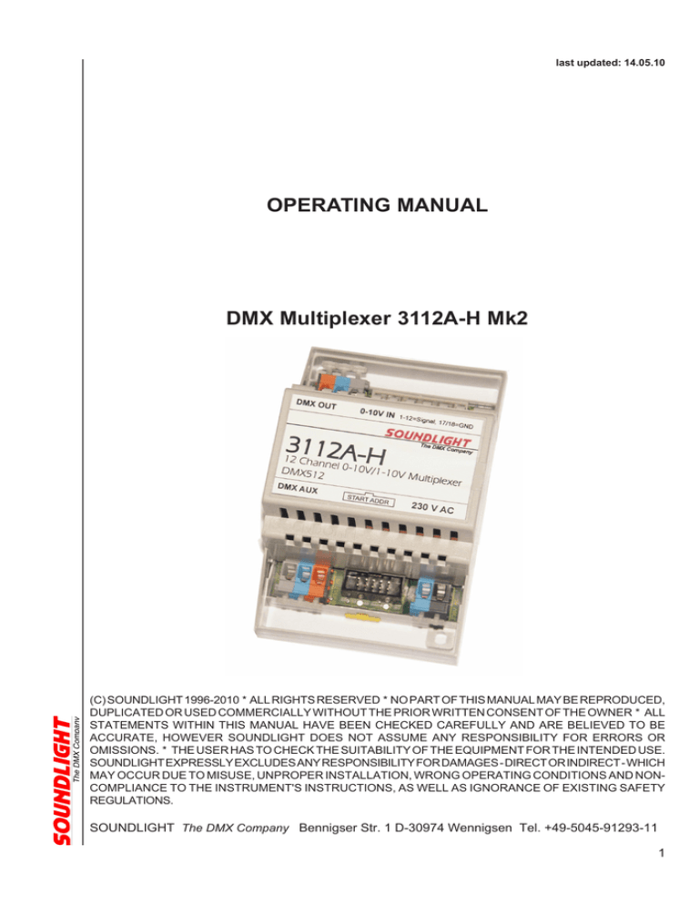
DMX Multiplexer 3112A-H Mk2
(C) SOUNDLIGHT 1996-2010 * ALL RIGHTS RESERVED * NO PART OF THIS MANUAL MAY BE REPRODUCED,
DUPLICATED OR USED COMMERCIALLY WITHOUT THE PRIOR WRITTEN CONSENT OF THE OWNER * ALL
STATEMENTS WITHIN THIS MANUAL HAVE BEEN CHECKED CAREFULLY AND ARE BELIEVED TO BE
ACCURATE, HOWEVER SOUNDLIGHT DOES NOT ASSUME ANY RESPONSIBILITY FOR ERRORS OR
OMISSIONS. * THE USER HAS TO CHECK THE SUITABILITY OF THE EQUIPMENT FOR THE INTENDED USE.
SOUNDLIGHT EXPRESSLY EXCLUDES ANY RESPONSIBILITY FOR DAMAGES - DIRECT OR INDIRECT - WHICH
MAY OCCUR DUE TO MISUSE, UNPROPER INSTALLATION, WRONG OPERATING CONDITIONS AND NONCOMPLIANCE TO THE INSTRUMENT'S INSTRUCTIONS, AS WELL AS IGNORANCE OF EXISTING SAFETY
REGULATIONS.
SOUNDLIGHT The DMX Company Bennigser Str. 1 D-30974 Wennigsen Tel. +49-5045-91293-11
1
Thank you for choosing SOUNDLIGHT products.
The SOUNDLIGHT DMX Multiplexer 3112A-H will convert analog input voltages to digital DMX512
signals according to USITT DMX512/1990 (United States Institute for Theatre Technology,
www.usitt.org) or DIN56930-2 (www.din.de). All types of equipment labeled with "DMX-512" or "DMX512/1990" may be connected.
Advantages of the DMX multiplexer 3112A-H include:
- addressable
The start address of the output signal may be selected by rotary BCD switches. All 512 DMX
channels can be selected.
- extended channel count
The interface supports up to 12 analog inputs.
- buffered output
The DMX data output is actively buffered.
- simple supply
The supply voltage is 230V AC. All printed circuit boards are equipped with on-board stabilized
voltage regulators.
- high safety level
The multiplexer uses low voltage throughout.
- cost effective
The SOUNDLIGHT 3112A-H DMX multiplexer is a cost effective solution to retrofit existing legacy
equipment based on standard 0...+10V control.
CONNECTORS
The DMX multiplexer 3112A-H features these connectors:
CN1
POWER SUPPLY
1
2
CN2
AUX OUT
CN3
DMX OUT
2-pin Connector
blue
0V AC (N)
black
230V AC (L)
3-pin
1
2
3
connector
grey
blue
orange
GND,Shield
DMX DMX +
3-pin
1
2
3
connector
grey
blue
orange
GND, Shield
DMX DMX +
2
CN4 ANALOG IN
1
2
3
4
5
6
7
8
9
10
11
12
13
14
15
16
17
18
19
20
Pin 2
20-pin connector
CN3
Analog input 1
Analog input 2
Analog input 3
Analog input 4
Analog input 5
Analog input 6
Analog input 7
Analog input 8
Analog input 9
Analog input 10
Analog input 11
Analog input 12
nc
nc
nc
nc
Shield, 0V, GND
Shield, 0V, GND
+5V stab out
+10V DC stabilized out
CN4
CN5
CN2
CN1
Pin 20
Pin 1
SIGNALANZEIGEN
The Multiplexer 3112A-H consists of two signalling LEDs:
red:
Standby
green: unit is active, at least one input signal is present.
UNPACKING
Please unpack carefully and check that all items complete and are intact. When leaving our factory,
the card has been in good condition. In case of damage during transport please notify the carrier
immediately. Without a written and carrier acknowledged report we cannot process damaged
shipments.
When unpacking, you should identify these items:
*
the interface 3112A-H
*
this manual
IMPORTANT NOTICE:
All decoders intended for DIN rail mount may need a DMX start address board to set the desired
start address. DMX start address boards cat no. 3000P (switches) or 3003P (display) may be used.
Since one start adress board can be used to program any DIN rail unit this is NOT contained with
this product and must be ordered separately.
3
0-10V / 1-10V
The multiplexer can be used for signal input voltages from 0..10V or 1...10V,respectively. (to change
the input range see chapter "DIP SWITCHES"). If active inputs are required to comply with
unpowered 1-10V driving gear, please proceed as follows:
- Connect a 2k2 resistor from each signal input to pin 20/CN1 or to +12V DC
SIGNALLING
Upon connection of power (230V AC) to connector CN2 (see page 2) the multiplexer is ready to work.
The red LED will light. As soon as any signal input (1-12) is driven from an input voltage of more than
100mV the green LED will come up to indicate activity.
SWITCH SETTINGS
To program the multiplexer configuration the DMX start address
board may be connected to CN5. The multiplexer may be used
with or without start address board connected; if the board is
diconeccted the last valid settings will be retained in nonvolatile
memory. The DMX start address denotes the data slot number
starting with analog input #1, followed by inputs #3 thru #12. All other data slots (above
and below) will be transmitted as ZERO.
DIP-SWITCHES
The DIP switches are used to configure the multiplexer.
DIP-SWITCH 1
DIP-SWITCH 2
DIP-SWITCH 3
DIP-SWITCH 4
OFF:
ON:
OFF:
ON:
OFF:
ON:
OFF:
ON:
Normal
Switch mode activated
input voltage 0...+10V DC
input voltage 1...+10V DC
Normal
AUX OUT enabled
Normal
AUX OUT triggered from input #12
(see chapter: Trig-Mode)
TRIG-MODE
The multiplexer features two independent DMX outputs. One output is permanent, the other output
(AUX) can be activated by DIP-switch (see DIPswitch #3) or remotely via input signal#12 (see DIP
switch #4).
When using analog input #12 to trigger the AUX output, the output will only be activated if the input
signal exceeds 50% (or 5v, respectively). When disabled, the output line is idle (tri-state mode). No
other DMX512 output should be connected to this output.
4
TESTMODI
The DMX multiplexer contains test programs to easily verify the correct operation of the DMX512
data link. These functions may be called via special start address settings.
Test addresses include:
801...812
single channel outut 100%
997
test program "blink"
998
test program "fade"
999
test program "running light"
Test program settings are NOT retained in memory and thus can only be invoked with a start
address board attached to the multiplexer.
TECHNICAL DATA
Dimensions:
Weight:
Power Supply:
DMX OUT:
Order code:
65 mm x 105 mm x 65 mm
ca. 278 g
230V AC approx. 2 W
>20 Unit Load, buffered
3112A-H
DISTURBANCES
If a trouble-free operation cannot be guaranteed, disconnect the relay card interface and secure it
against unwanted operation. This is especially necessary, when
- the unit has visible damages;
- the unit does not operate;
- internal parts are loose;
- connection cables show visible damages.
LIMITED WARRANTY
This instrument ist warranted against defects in metarials and workmanship for a period of 12
month, beginning with the date of purchase. The warranty is limited to repair or exchange of
thehardware product; no further liability is assumed. SOUNDLIGHT is not responsible for damages
or for loss of data, sales or profit which arise from usage or breakdown of the hardware product. In
germany, SOUNDLIGHT will repair or replace established defects in hardware, provided that the
defective part is sent in, freight paid, through the responsible dealer along with warranty card and/or
sales receipt prior to expiration of warranty.
Warranty is void:
- when modifying or trying to repair the unit without authorisation;
- modification of the circuitry;
- damages by interference of other persons;
- operation which is not in arccordance with the manual;
- connection to wrong voltage or current;
- misuse.
5
CE CONFORMITY
This DMX demultiplexer is microprocessor controlled and uses high frequency (16 MHz quartz). The
interface has been tested in our EMC lab to comply with EN5022B and IEC65/144.
To ensure the best performance regarding radiated and conducted emissions we
suggest to install the interface card in a closed, conductive (e.g. metal) housing,
which must be connected to GND.
Please make sure that shielded data cable is used and the shield is connected
properly to the GND pin. Shield must never make contact to other signal lines.
FCC STATEMENT
This product has been tested and complies with the specifications for a Class B digital device,
pursuant to Part 15 of the FCC Rules. These limits are designed to provide reasonable protection
against harmful interference in a residential installation. This equipment generates, uses, and can
radiate radio frequency energy and, if not installed and used according to the instructions, may
cause harmful interference to radio communications.
However, there is no guarantee that interference will not occur in a particular installation. If this
equipment does cause harmful interference to radio or television reception, which is found by turning
the equipment off and on, the user is encouraged to try to correct the interference by one or more of
the following measures:
• Reorient or relocate the receiving antenna
• Increase the separation between the equipment or devices
• Connect the equipment to an outlet other than the receiver's
• Consult a dealer or an experienced radio/TV technician for assistance
FCC Caution: Any change or modification to the product not expressly approved by SLH could void
the user’s authority to operate the device.
END OF LIFETIME
When the useful lifetime of this product has been reched, it must be disposed of
properly. Electronic devices must not be placed in domestic waste. Consult your local
authorities to find the nearest collection point of used electric and electronic devices.
SOUNDLIGHT is a WEEE registered company (Reg Nr. DE58883929).
SERVICE
There are no parts within the DMX multiplexer 3112A-H which require the user's attention. Should
your unit require servicing, please send it to the factory, freight paid.
6


