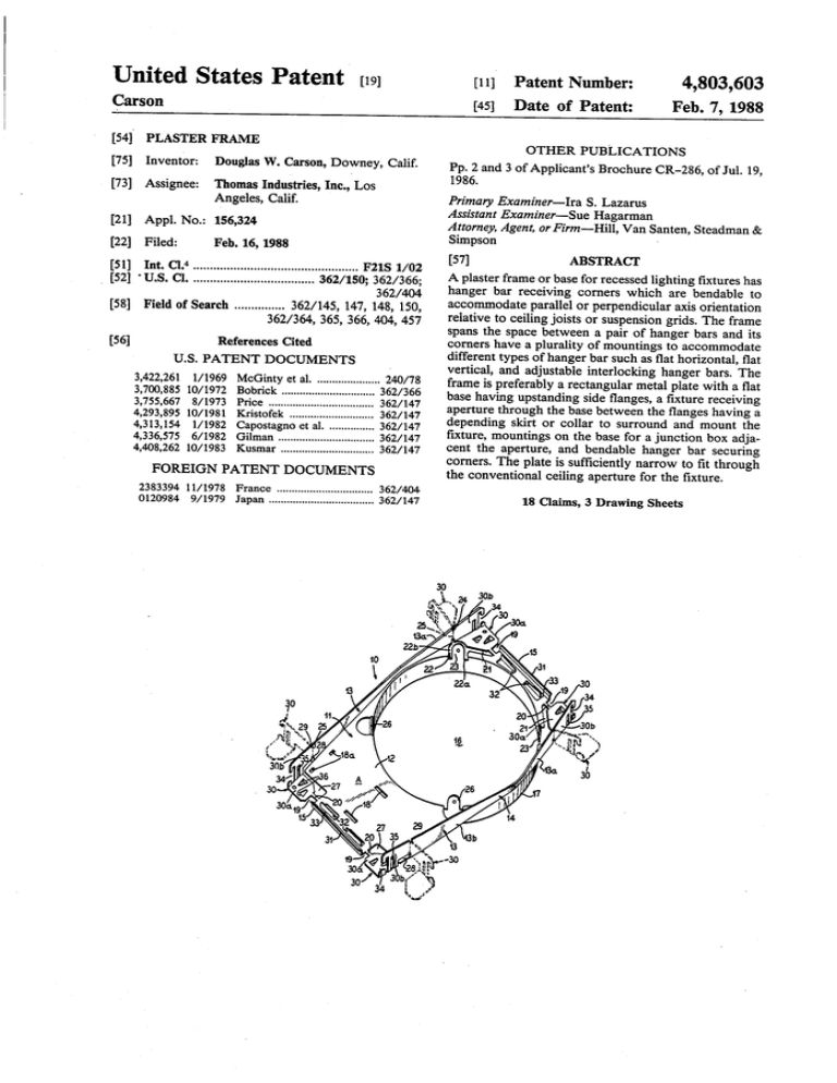
Plaster frame
advertisement

United States Patent [19] Carson [11]v Patent Number: [45] 4,803,603 Date of Patent: Feb. 7, 1988 [54] PLASTER FRAME [75] Inventor: Douglas W. Carson, Downey, Calif. [73] Assignee: Thomas Industries, Inc., Los Angeles, Calif. [21] Appl. No.: 156,324 [22] Filed: [51] Primary Examiner-Ira S, Lazarus Assistant Examiner—Sue Hagarman Attorney, Agent, or Firm-Hill, Van Santen, Steadman & Simpson Feb. 16, 1988 Int. Cl.4 ............................................... .. F21S 1/02 _ [52] ‘U.S. Cl. .................................. .. 362/150; 362/366; 362/404 [58] Field of Search ............. .. 362/145, 147, 148, 150, 362/364, 365, 366, 404, 457 [56] _ 1/ 1969 McGinty et al. ................... .. 240/78 Bobrick ....... .. Price ........ .. Kristofek ..... .. 6/1982 4,408,262 10/1983 Gilman ............. .. different types of hanger bar such as ?at horizontal, ?at vertical, and adjustable interlocking hanger bars. The frame is preferably a rectangular metal plate with a ?at base having upstanding side ?anges, a ?xture receiving depending skirt or collar to surround and mount the .. 362/147 Kusmar ............................. .. 362/147 FOREIGN PATENT DOCUMENTS 2383394 11/1978 0120984 9/1979 accommodate parallel or perpendicular axis orientation relative to ceiling joists or suspension grids. The frame aperture through the base between the ?anges having a 4,313,154 l/ 1982 Capostagno et al 4,336,575 ABSTRACT A plaster frame or base for recessed lighting ?xtures has hanger bar receiving corners which are bendable to corners have a plurality of mountings to accommodate U.S. PATENT DOCUMENTS 3,700,885 10/1972 3,755,667 8/1973 4,293,895 10/1981 [57] - spans the space between a pair of hanger bars and its References Cited 3,422,261 OTHER PUBLICATIONS Pp. 2 and 3 of Applicant’s Brochure CR-286, of Jul. 19, 1986. France .............................. .. 362/404 Japan ................................. .. 362/147 ?xture, mountings on the base for a junction box adja cent the aperture, and bendable hanger bar securing comers. The plate is suf?ciently narrow to ?t through the conventional ceiling aperture for the ?xture. 18 Claims, 3 Drawing Sheets US. Patent Feb. 7, 1989 Sheet 1 of3 4,803,603’ US. Patent Feb. 7, 1989 Sheet 2 of3 4,803,603 US. Patent Feb. 7, 1989 Sheet 3 of3 4,803,603 1 4,803,603 2 which rest on the base portions of the corners. Vertical IPLASTER FRAME FIELD OF THE INVENTION This invention relates to the art of mounting recessed lighting ?xtures and speci?cally deals with a universal plaster frame or base plate carrying the lighting ?xture and a junction box and having bendable hanger bar receiving corners accommodating alternate alignments of the ?xture assembly relative to ceiling joists or grids. BACKGROUND OF THE INVENTION Heretofore plaster frames or base plates for recessed lighting fixtures were not universally suitable for all types of installation and had to be supplied in different con?gurations to - accommodate different alignment requirements. This frequently resulted in installation delays because the installer did not have a modi?ed frame or base for a particular installation. Further, the closed periphery slots are provided inwardly from the gapped slots to receive ?at vertical hanger bars resting on the ?at base portions of the corners. These base portions then have lanced out tabs depending therefrom to straddle underlying horizontal ?at type hanger bars on which rest the base portions of the corners. The ?at base portion of the plate has circumferen tially spaced upstanding tangs or ears around the aper ture and the ?at base area alongside the aperture has tang receiving slots. The “Can” or housing of the re cessed lighting ?xture ?ts snugly through the aperture surrounded by the collar and is secured to the plate by fasteners anchored in the upstanding tangs or ears around the aperture. A junction box is conveniently mounted on the ?at end portion of the plate between the ?anges by means of tangs depending from the box through the slots in the base. necessity for manufacturing and maintaining invento 20 The hanger bars are conventionally mounted on ries of many different types of frames or base plates caused confusion and greatly increased the costs. Further, the prior known plaster frames or base plates for recessed lighting ?xtures were too wide for insertion through the ?xture receiving ceiling aperture and had to be provided with a break out section opening up a gap permitting the plate to straddle the ceiling and then be rotated through the aperture. This procedure was, of course, quite awkward. spaced parallel ceiling joists, ceiling suspension grids and the like, spanning the space between the adjacent joists and grids. The plaster frame or base plate can slide along the hanger bars to the exact position desired for the recessed ?xture and to register with a ceiling open ing for the ?xture. In some installations the axis of the ?xture is parallel to the joists or grid supports while in other installations It would therefore be an improvement in this art to 30 this axis is perpendicular to the support joists or grids and in order to provide for alignment of the ?xture in provide a universe plaster frame or base plate for re these different installations it is necessary to change the cessed lighting ?xtures accommodating all different axis position of the frame between the joists or grids. types of hangers and installation orientations and capa This is accomplished by leaving the corners in their ble of being inserted through ?xture receiving ceiling apertures without modi?cation. SUMMARY'OF THE INVENTION According to this invention, a plaster frame or base 35 longitudinal positions to have the axis parallel with the joists and to bend the corners laterally outwardly at right angles to their longitudinal positions to have the axis perpendicular to the joists or grids. plate for recessed lighting ?xtures has bendable hanger Many different stamping patterns may be provided bar receiving comers accommodating all conventional 40 for the plaster frame but it is generally preferred to have types of hanger bars and adapted to extend axially or a generally rectangular metal plate with sides converg laterally to accommodate axial or transverse installa ing from both sides of the collar at its transverse diame tions and to fit through conventional ceiling apertures ter so that the ends of the plate are narrower than the for recessed lighting ?xtures. exterior diameter of the collar. This facilitates insertion The preferred frame is a ?at metal plate of generally 45 of the plate through the ceiling aperture for the ?xture. rectangular con?guration having a base with upstand The plaster frames or base plates of this invention ing ?anges or skirts along the sides thereof, a lighting may vary in size for different sized recessed lighting ?xture receiving aperture through the base between the ?xtures but are preferably formed of galvanized steel ?anges having a depending integral collar, a ?at junc about 0.03125" to 0.0336" inches thick. For conven tion box receiving area on the base along one side of the 50 tional cylindrical “Can” type recessed ?xtures, the plate aperture, four independent comers each composed of will have a length of about 10.19" to 10.21” inches, a end portions of the ?anges and adjacent ?at base por maximum width of 6.39 to 6.42 inches, reduced width tions and living hinge or bending zones connecting the ends about 4.99 to 5.01 inches wide, upstanding ?anges ?ange portions of the corners to the main ?anges. The of about 0.89 to 0.91 inches high, an aperture of about corners thus have horizontal ?at base portions and up right side portions and are adapted to bend along the hinge line from longitudinal or axial positions to trans 55 6.23 to 6.25 inches in diameter and a depending skirt or collar about 0.64 to 0.66 inches deep. The corners are about 0.88 to 1.00 inches long and 0.85 to 1.00 inches wide. The ends of the ?at plate are bent upwardly from the A preferred embodiment of the invention is illus base providing transverse ribs between the corners. 60 trated in the drawings in which: Fingers are lanced up from the base inwardly and paral FIG. 1 is a top and side perspective view of a plaster lel to the ribs to cooperate with the ribs to straddle frame or recessed lighting ?xture base plate of this in overlying hanger bars. vention with dotted line illustrations of the corners of The corners are provided with slots and tangs for the plate showing the alternate mounting position. verse or lateral positions. mounting the plate on all types of conventional hanger bars. Thus, the upstanding ?ange portions of the cor ners have outermost vertical slots with outwardly open ing gaps to receive conventional extensible hanger bars FIG. 2 is a side and bottom perspective view of the base plate of FIG. 1 carrying a cylindrical lighting ?x ture and conduit box and mounted on extensible hanger bars. 3 4,803,603 FIG. 3 is a side and top fragmental perspective view showing the plaster frame mounting between ceiling 4 28 in the corner between the base 12 and the ?ange 13. A notch 29, identical with the notch 23, is formed in the to FIG. 3 of a perpendicular axis mounting between joists accommodated by the plaster frame of this inven top edge of the ?ange 13 just above the inner end of the slot 28 to provide the same type of bending line 25 as is provided at the opposite end of the base. The slots 19, 21, 22 and 19, 27, 28 thus provide four tion. independent corner tabs 30 each having a bottom base FIG. Sis a perspective view illustrating the manner in which the plaster frame is easily inserted through a segment 30a and an upstanding ?ange segment 30b and which, when the bridge 20 is severed, can swing about the hinge line 25 from an axially extending position to joists or rafters on an axis parallel with the joists. FIG. 4 is fragmentary top diagrammatic view similar ceiling opening for the recessed lighting ?xture. FIG. 6 is a fragmentary front corner perspective view illustrating the manner in which the plaster frame is mounted on ?at vertical hanger bars in alternate axial positions. the radially extending position. The portions of the ends 15 between the slots 19 are turned upwardly to provide tranverse ribs 31. The base 12 adjacent each'rib 31 is lanced to provide a pair of transverse tangs 32 paralleling the rib 31 and providing FIG. 7 is a view similar to FIG. 6 but illustrating the manner in which the plaster frame may be alternately mounted on horizontal ?at hanger bars. therebetween a track 33 for a hanger bar as will later be “joist” is intended to include suspended ceiling grids conventionally used in dropped ceiling mountings and adjustable interlocking vertical hanger bars B (FIG. 2) described. Each comer 30 has an outwardly opening “C” BRIEF DESCRIPTION OF THE PREFERRED shaped vertical slot 34 in the ?ange portion 30b thereof ILLUSTRATED EMBODIMENT 20 aligned with the track 33. A closed periphery vertical In the drawings, the reference numeral 10 designates slot 35 is also formed through each ?ange portion 30b in generally, a plaster frame of this invention for mounting spaced parallel relation behind the “C” shaped slot 34. a lighting fixture F on hanger bars B secured to adjacent The base 30a of each corner 30 has a pair of confront spaced parallel joists or rafters R and spanning the space ing tangs 36 lanced therefrom and cooperating to de?ne therebetween in spaced parallel relation or perpendicu a hanger bar strap under each corner base 300. lar to the rafters. As used herein, the term “rafter” or The “C” shaped slots 34 and the tracks 33 receive to suspend the plaster frame from the rafters R as illus other structural beams or building supports for electri trated in FIG. 3. In this illustrated arrangement, the 30 cal ?xtures. corners 30 are in their normal axially extending posi The plaster frame 10, as best shown in FIGS. 1 and 2, tions and the plaster frame has its axis parallel to the is a generally rectangular metal plate 11 with a ?at base 12 having upturned ?anges or skirts 13, 13 along the length thereof. The base has a wide intermediate por tion 14 and tapers from this wide portion to narrower end portions 15, 15. Each ?ange 13 therefore has a short leg portion 13a converging from the wide portion 14 to one end 15 and a longer leg portion 13b converging from the wide portion 14 to the opposite end 15. A large diameter aperture 16 is provided through the rafters and adjustable along the length of the hanger bars to align the lighting ?xture with a ceiling aperture. When the corners 30 are bent laterally outward on, their hinge lines 25, these slots 34 open laterally out~ ward and receive the expansible hanger bars B along the sides of the plaster frame instead of along the ends. Thus, an outturned corner at one end of the plaster 40 frame, cooperates with a corresponding outturned cor ner at the opposite end of the frame to suspend the frame from the hanger bar B and provide a perpendicu lar axis mounting between joists or rafters R at right ing of the aperture 16 adjacent one end of the plate 11 angles to the rafters or joists illustrated in FIG. 3, as provides a platform area A on the base for receiving a standard electrical junction box C. This box C has de 45 shown in FIG. 4. The transverse or perpendicular axis wide portion 14 of the base 12 and is surrounded by an integral depending cylindrical collar 17. The position pending ears E (FIG. 2) extending into slots 18 in the platform A (FIG. 1) to center the box on the platform arrangement permits the lighting ?xture to be moved into alignment with a ceiling aperture between the and tangs T locked in slots 18a to secure the box to the base 12. Each corner of the base is separated therefrom by a joists. slot 19 extending axially or longitudinally inward from S on their ends which are driven into the rafters R (FIGS. 3 and 4) to mount the bars in an upright vertical the end 15 to a narrow transverse break away bridge 20. At one end 15 (the top end of FIG. 1), a diagonal slot 21 extends axially inwardly and radially outwardly from As illustrated in FIG. 2, the adjustable hanger bars B each have a pair of slidably connected strips with spikes position. As shown in FIG. 6, each corner 30 also accommo the bridge 20 to a U-shaped slot 22 having legs 22a and 22b opening into the aperture 16 and thus providing a tab 23 which is bent upwardly at the top of the collar. dates the so-called ?at vertical hanger bar B; which overlies the plaster frame and extends through the closed periphery slot 35 of the corner ?ange 30b. The The slot leg 22b is extended into the adjacent ?ange leg corners 30, of course, can be positioned axially, as illus trated in solid lines or bent laterally outward, as illus 13a and a notch 24 is cut in the top edge of the ?ange leg 13a to provide a bending line 25 in the ?ange between 60 trated in dotted lines to suspend the plaster frame from the vertical hanger bars B1 on parallel or perpendicular the notch and slot leg. axes between the rafters or joists. Two other upstanding tabs 26 are lanced from the As shown in FIG. 7, the plaster frame 10 is also capa platform A at the collar 17 to provide four equal cir ble of beingmounted on horizontal ?at hanger bars B2 cumferentially spaced tabs extending above the collar. The opposite platform end 15 of the base 12 has a 65 . In this arrangement the frame is positioned on the top of the ?at bars and the downturned tangs 36 of the base slightly modified slot inwardly from the bridge 20 portions 30a of the corners 30 lap around the sides of the which extends radially as shown at 27 to the longer arm hanger bars B2 providing a guide track for the hanger 13b of the ?ange 13 and then extends longitudinally at 5 4,803,603 bars and holding the plaster frame to span the space 6 corners for selectively receiving different types of hanger bars to mount the frame between building joists. 3. A universal plaster frame for recessed lighting ?xtures adapted for insertion through an opening sized to receive the ?xture and for mounting axially parallel between the parallel hanger bars. It will thus be understood from the showings in FIGS. 2, 6 and 7, that the plaster frame corner accom modates conventional different types of hanger bars. As shown in FIG. 2, the can 40 of the lighting ?xture or perpendicular to ceiling joists on ?at horizontal, ?at F snugly ?ts in the collar 17 of the plaster frame 10 and is secured to the collar by screws 41 extending through slots 42 thereof and threaded into the tangs 23 and 26 of the collar. The slots 42 accommodate raising and lower ing of the can 40 relative to the plaster frame 10. A lighting socket (not shown) in the dome of the can 40 is vertical, and adjustable interlocking types of hanger bars which comprises a plate having a lighting ?xture receiving aperture surrounded by an integral depending collar, upturned ?anges on two sides of the plate, iso lated corner portions on the plate having supports for any of such types of hanger bars and hinges connecting the corner portions with the ?anges to selectively posi connected through an external Bx conduit 43 with the tion the hanger bar supports to accommodate the axial conduit box C mounted on the platform portion A of 15 and perpendicular mountings. the plaster frame. 4. The frame of claim 3 wherein the corner portions As illustrated in FIG. 5, the plaster frame 10 with the conduit box C thereon ‘coupled to the socket in the have bases and ?anges with hanger bar receiving means. demounted plaster can 40 through the Bx conduit 43 5. The frame of claim 3 wherein the corner portions and to an electrical conduit 44 emerging from above the 20 swing from axial alignment with the plate to outturned lateral positions. ceiling 45 through a ?xture aperture 46, is easily in serted through the ceiling aperture sized for the re 6. The frame of claim 3 including severable bridges connecting the corners to the plate. cessed lighting ?xture without interference since the 7. The frame of claim 3 including a platform on the narrow plaster frame of this invention ?ts easily through this aperture. The frame is then mounted on the 25 plate at one side of the aperture and means for mounting a conduit box on the platform between the flanges. hanger bars above the ceiling and the ?xture is pushed 8. The frame of claim 3 wherein the plate is rectangu through the aperture 16 and secured to the frame by the lar, the ?anges are on the long sides of the plate and the screws 41. The ?xture is then mounted for use. ends of the plate are narrower than the inner portions. From the above descriptions and illustrations of the 9. The frame of claim 8 wherein the ends of the plate drawings, it should be understood that this invention have hanger bar tracks between the corners. provides a universal'plaster frame for recessed lighting 10. The frame of claim 3 wherein the plate is a ?xtures which will accommodate conventional hanger punched and stamped metal piece. bars and parallel and perpendicular axis mountings. 11. The frame of claim 3 wherein the hanger bar While a particular embodiment of the plaster frame has 35 supports slidably receiving the hanger bars. been described and illustrated in detail, it should be understood that many different stamping designs are 12. The frame of claim 2 wherein the corners have ?at base portions and upstanding ?ange portions con nected to the ?anges and swingable thereabouts from axial to lateral positions. available to accommodate the formation of the bend able comers from a sheet metal plate and that apertures of different shapes and sizes can be formed in the plate 40 13. The frame of claim 2 wherein the plate is a one piece metal stamping. for different types of recessed lighting ?xture. It will therefore be understood that the scope of this 14. The frame of claim 2 wherein the base has a plat form area alongside the aperture and means on the plat invention is to be determined only as de?ned in the form for anchoring a conduit box thereon. claims. 45 15. The frame of claim 14 wherein said means for I claim as my invention: anchoring are tangs carried from the base. 16. The frame of claim 12 wherein the base portions 1. A plaster frame for recessed lighting ?xtures which comprises a ?at metal plate, an aperture through the of the corners are connected to the base of the plate by plate, a collar depending from the aperture, and bend able corners on the plate swingable from axial to trans severable bridges. 17. A recessed lighting ?xture assembly including the -verse positions and constructed and arranged to receive hanger bars for mounting the frame in axial and perpen dicular orientations between joists. 2. A plaster frame for recessed lighting ?xtures which comprises a generally rectangular metal plate having an apertured ?xture receiving ?at base with upturned side frame of claim 2 having a ?xture can anchored in the aperture of the frame, a conduit box anchored on the ?at base of the frame and an electrical conduit connect ing the box and can. 55 flanges, corners on the base swingable on said ?anges from axial to transverse positions and means on said 18. The frame of claim 1 including tabs bent from the plate around the collar for receiving fasteners to secure the ?xture in the collar. * 65 * =8 * *


