Model 781 Signal Conditioning Unit
Model 781 is a precision, two-channel signal
conditioning unit for all electrolytic tilt
sensors. Its design is optimized to produce
peak performance from your Applied
Geomechanics 755-, 756-, 757-and 758-Series
Miniature Tilt Sensors.
Signal unit for electrolytic tilt
sensors
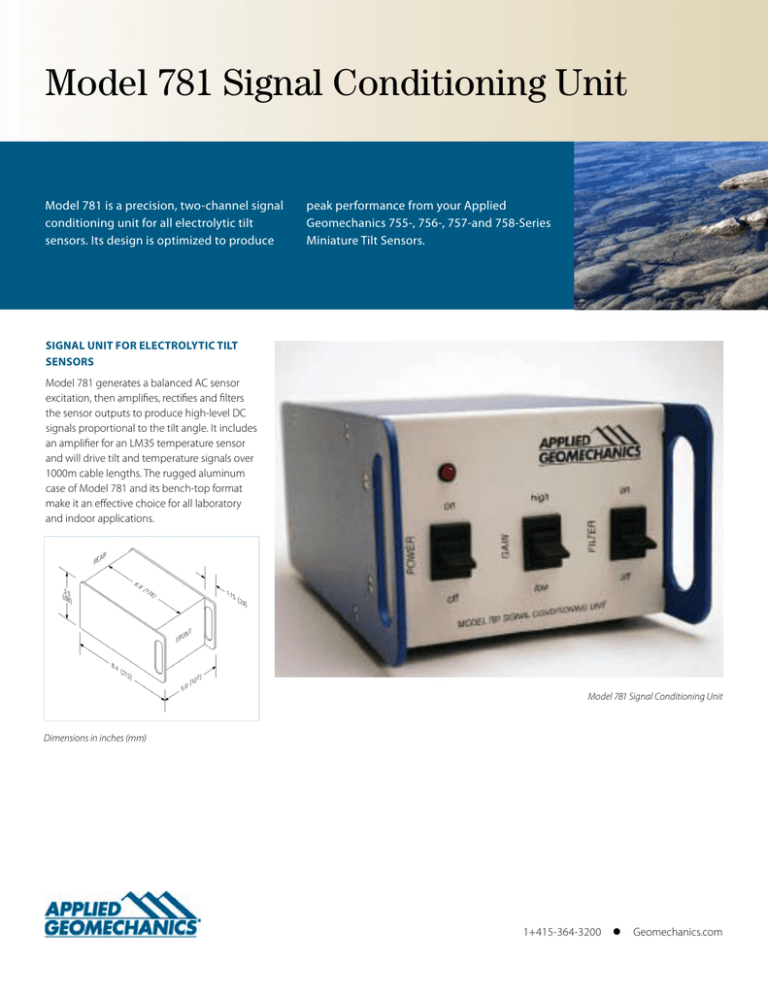
Model 781 generates a balanced AC sensor
excitation, then amplifies, rectifies and filters
the sensor outputs to produce high-level DC
signals proportional to the tilt angle. It includes
an amplifier for an LM35 temperature sensor
and will drive tilt and temperature signals over
1000m cable lengths. The rugged aluminum
case of Model 781 and its bench-top format
make it an effective choice for all laboratory
and indoor applications.
Model 781 Signal Conditioning Unit
Dimensions in inches (mm)
1+415-364-3200
l
Geomechanics.com
Model 781 Signal Conditioning Unit
INPUT CHANNELS
Two electrolytic tilt sensors, one LM-35 temperature sensor (included with tilt sensors)
TILT OUTPUT
Two single-ended and two differential analog outputs, proportional to tilt: Output voltage range: ±8 VDC (single-ended), ±16 VDC (differential)
OUTPUT GAINS
Two switchable gains, 10:1 ratio standard, other ratios on request
SCALE FACTORS†
When used with:
755-Series Sensors:
756-Series Sensors:
757 & 758-Series Sensors:
High-Gain
0.1 µradian/mV*
0.1 degree/V
1.0 degree/V
Low-Gain
1.0 µradian/mV
1.0 degree/V
10 degrees/V
Range
±8000 µradians
±8 degrees
±60 & ±80 degrees
OUTPUT FILTERS
Two switchable low-pass integrators, roll-off = 6 dB/octave. Time constants = 0.05 and 7.5 seconds, other settings on request
TEMPERATURE OUTPUT
0.1°C/mV (single-ended), –40° to +100°C, ±0.75°C accuracy, 0°C = 0 mV
OUTPUT IMPEDANCE
270 ohms, short circuit and surge protected
POWER REQUIREMENTS
±11 to ±15 VDC @ +11 and -6 mA typical, 250 mV peak-to-peak ripple max., reverse polarity protected
POWER REQUIREMENTS
+11 to +15 VDC and -11 to -15 VDC @ +15 mA and -7 mA typical; 250 mV peak-to-peak ripple max. Reverse polarity and surge protected. Low battery indicator on switch plate.
CONNECTIONS
15-pin quarter-turn connectors on tiltmeter and switch box, connected by 3m (10 ft) multiconductor cable. Power and signal connections made via terminal strip in switch box.
CONNECTIONS
Dual screw-terminal barrier strips on rear panel
ENVIRONMENTAL
-25° to +70°C operational, -30° to +100°C storage; 0 to 90% humidity, noncondensing
MATERIALS
Painted aluminum case
SIZE & WEIGHT
3.5 x 5 x 8.4 inches (88 x 127 x 213 mm), 2 lb (0.9 kg)
* 1 degree = 3600 arc seconds = 17453 µradians (microradians) † Single-ended outputs; divide by 2 for differential scale factors.
USEFUL ACCESSORIES:
Model D12-200 ±12 Volt DC Power Supply
P/N 81124-03 Spare temperature sensor with 18-inch (450mm) pigtail
Front View
Model 781 Signal Conditioning Unit
©2009 Applied Geomechanics, Inc. All Rights Reserved. 09.09/X
Rear View


