Thin Solid Films 351 (1999) 61±65
Ultraviolet ray absorbing coatings on glass for automobiles
Takeshi Morimoto*, Hiroyuki Tomonaga, Akemi Mitani
Research Center, Asahi Glass Company, 1150 Hazawa-cho, Kanagawa-ku, Yokohama-shi 221-0863, Japan
Abstract
Ultraviolet ray (UV) absorbing coating consisting of a complex oxide of cerium and titanium was deposited on glass via the sol±gel
process. Addition of TiO2 to CeO2 changed the crystallinity and coordination state of CeO2 and improved UV absorption. Formation of a
double-layered coating comprised of outer CeO2±TiO2 layer and inner TiO2±SiO2 layer diminished the interference coloring and improved
the adhesion of the coating to the glass substrate. The double layer coated glass shows high UV-shielding properties without visible light
absorption and excellent durability against chemical and physical attacks. Therefore, it has been widely used in automobile windows. q 1999
Elsevier Science S.A. All rights reserved.
Keywords: Sol±gel process; Ultraviolet absorption; Optical coating; Spin-coating
1. Introduction
2. Experimental
Excessive exposure to ultraviolet rays (UV) in sunlight
(6%) induces coloring and deterioration in paper, fabrics
and resins. It also causes harmful damage to the human
body such as premature aging of skin, skin cancer and cataract. Recent destruction of the ozone layer around the earth
increases UV irradiation and its harmful effect on the human
body [1]. Shielding from UV irradiation is of interest in
many ®elds. For automobile applications, it is necessary
to prevent the interior materials and the skin of passengers
from damaging by UV. For this purpose, we have developed
an UV-shielding coating comprised of two metal oxides.
It is well known that glass containing mixed oxides of
cerium and titanium absorb UV effectively and exhibit
yellow color [2]. It is also reported [3,4] that CeO2±TiO2
coatings deposited on glass by the sol±gel process show
UV absorption, high re¯ectance and interference coloring.
However, its UV absorption is not suf®cient because of its
composition of CeO2 =TiO2
1:0. Moreover, high re¯ectance
and interference coloring are not preferable for automobile
windows.
The present research was performed to solve the abovementioned problems. An attempt was made to (1) maintain
CeO2/TiO2 ratio above 1.0 to increase UV absorption, and
(2) form a double-layered coating on glass to diminish
re¯ectance and coloring. This paper describes the materials,
mechanisms and properties of the double layer coated glass.
2.1. Coating solution for outer UV absorbing layer
* Corresponding author. Tel.: 181-45-374-8810; fax: 181-45-3748858.
E-mail address: morimoto@agc.co.jp (T. Morimoto)
Cerium nitrate hexahydrate (Daiichi Kigenso Co.) and
titanium n-butoxide (TBT, Matsumoto Kosho Co.) were
used as metal precursors of metal oxides. TBT was
dissolved in ethanol and the solution was stirred for 1 h at
258C. An aqueous solution of 6 wt.% HCl was added to the
solution of TBT. The molar ratio of H2O/TBT was 8.5.
Concentration of this solution was 0.8 M as Ti (Solution
A). Cerium nitrate hexahydrate was dissolved in ethanol.
Then, polyethyleneglycol (PEG, average molecular weight
200) and acetylacetone (AA) were added as multidentate
ligands. The molar ratio of Ce/PEG/AA was adjusted to
1:1:1. The obtained solution was heated up to 708C for 2
h and cooled to room temperature (Solution B). Concentration of solution B was also 0.8 M as Ce. Solutions A and B
were mixed in various ratios and aged at 358C for 1 day.
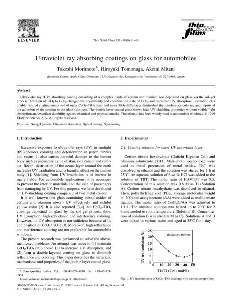
Fig. 1. UV transmittance of CeO2±TiO2 coatings with various composition.
0040-6090/99/$ - see front matter q 1999 Elsevier Science S.A. All rights reserved.
PII: S 0040-609 0(98)01779-9
62
T. Morimoto et al. / Thin Solid Films 351 (1999) 61±65
Fig. 3. XRD pro®le of CeO2±TiO2 coatings treated at 7008C for 3 and 60
min.
Fig. 2. XRD pro®le of CeO2±TiO2 coatings CeO2/TiO2 molar ratio:
(a)100:0, (b)80:20, (c) 70:30, (d) 60:40.
2.2. Coating solution for inner layer
Titanium isopropoxide (TPT, Mitsubishi Gas Chemical
Co.) and tetraethyl-orthosilicate (TEOS, Tama Chemical
Co.) were used as precursors for metal oxides. Various
ratios of TPT and TEOS were dissolved in a solution of
ethanol and acetylacetone (90:10 in weight ratio) and stirred
for 1 h at 258C. Then 1 wt.% HCl aqueous solution was
added to the solution under stirring to the molar ratio of
H2O/(TPT 1 TEOS) 2. Concentration of this solution
was 0.4 M as Ti1Si. Then the solution was aged at 358C
for 1 day.
2.3. Coating procedure and analysis
Polished and cleaned soda-lime silicate glass
(100 £ 100 £ 3:5 mm) was used as the substrate. Solution
was applied to the substrate using the spin-coating process.
After drying at 1208C for 5 min, the coated glass was heated
up to 7008C and ®red for 3 min.
The ®lm thickness was determined with a pro®lometer
(Sloan, Dektak 3030). The microstructure of the coatings
was observed with a scanning electron microscope (Hitachi,
S-900SEM). Crystal phases were determined with an X-ray
diffractometer (Rigaku, RINT-2000). Transmittance and
re¯ectance of the coatings were measured with a spectrophotometer (Hitachi, U-3500). State analysis was carried
out by ESCA (Phi, type5500) and ¯uorescent EXAFS
(Rigaku, R-EXAFS2000).
3. Results
3.1. CeO2±TiO2 UV absorbing coating
Fig. 1 shows the UV transmittance of glasses coated with
various CeO2±TiO2 binary compositions. Film thickness
was 160 nm for all coatings. The addition of TiO2 to CeO2
lowers UV transmittance in the composition range of CeO2/
TiO2 $1 and shows its minimum at around 40 mol%.
Although it was reported [4] that CeO2 precipitates in a
solution of the molar ratio of CeO2 =TiO2
1, no precipitation
occurred in any ratios of CeO2/TiO2 solutions used in this
experiment. Acetylacetone and polyethyleneglycol added to
Fig. 4. SEM surface photographs of CeO2±TiO2 coatings treated at 7008C for (a) 3 and (b) 60 min.
T. Morimoto et al. / Thin Solid Films 351 (1999) 61±65
63
Table 1
EXAFS results
Fig. 5. Transmittance spectra of CeO2±TiO2 coatings treated at 7008C for 3
and 60 min.
the solution seem to play important roles in stabilizing Ce
ions in the solution.
Fig. 2 shows XRD pro®les of various compositions of
CeO2±TiO2 coatings on glass. The coating containing only
CeO2 shows several peaks which have been indexed to the
cerianite, CeO2, crystalline structure. However, addition of
TiO2 to CeO2 coating decreases the crystallinity of cerianite
and forms a complete amorphous phase at the composition
of TiO2/CeO2 40:60. Moreover, the peaks indexed anatase
or rutile structure of TiO2 do not appear by the addition of
TiO2 up to 40mol%. This means that addition of TiO2 to
CeO2 increases disorder in the crystalline structure of cerianite.
Figs. 3 and 4 compare X-ray spectra and SEM surface
photograph of the CeO2/TiO2 60:40 coatings treated at the
temperature of 7008C for 3 min. and 7008C for 60 min. The
X-ray spectra and SEM surface photograph of the coating
treated at the temperature of 7008C for 60 min show the
peak indexed to cerianite, CeO2 and the precipitates below
50 nm, respectively. The precipitates are expected tobe
composed of cerianite. Fig. 5 compares UV transmittance
spectra of the coatings. The coating treated at the temperature of 7008C for 3 min absorbs UV effectively, whereas the
coating treated at 7008C for 60 min does not absorb UV
Fig. 6. ESR spectra of Ce 31 standard and CeO2±TiO2 coatings.
Sample
Coordination number of Ce
distance to
neighboring
O 22 (nm)
CeO2
CeO2TiO2
8.0 (standard)
6.2
0.234 ^ 0.002
0.233 ^ 0.002
effectively. These facts suggest that the amorphous phases
composed of TiO2/CeO2 play an important role in absorbing
UV.
As mentioned above, addition of TiO2 to CeO2 changes
crystallinity. It is supposed that these changes are caused by
some differences in the valence or coordination state of Ce
ion. ESR measurements at 6 K (liquid Helium temperature)
shown in Fig. 6 indicate that trivalent Ce 31 ions are not
present in both CeO2 100% and CeO2/TiO2 60:40 coatings. This means that only tetravalent Ce 41 ions are present
in both coatings. Table 1 shows the results of EXAFS analysis on Ce±L orbital in the CeO2 and CeO2±TiO2. Although
the addition of TiO2 to CeO2 does not change the distance to
neighboring O 22, it reduces the coordination number of Ce
ion to nearly 6. Considering that CeO2 takes ¯uorite structure of which the coordination number of Ce is 8 and TiO2
takes the anatase or rutile structure of which the coordination number of Ti is 6, it is expected that the structure of
CeO2 changes to anatase or rutile structure gradually by the
addition of TiO2 to CeO2.
3.2. Inner layer coating
The refractive index of UV absorbing layer is about 2.10
and higher than that of substrate glass (1.52). Therefore, the
glass coated by UV absorbing layer shows high re¯ectance
and re¯ection coloring owing to optical interference. The
inner layer was applied between the glass substrate and UV
absorbing layer in order to reduce the re¯ectance and re¯ection coloring. Refractive index and optical thickness
required for the inner layer coating were calculated to be
1.7±1.8 and 110±150 nm, respectively. Sol±gel derived
SiO2±TiO2 binary coatings were used as the inner layer.
Fig. 7. Refractive index of TiO2±SiO2 coatings with various compositions.
64
T. Morimoto et al. / Thin Solid Films 351 (1999) 61±65
Fig. 8. Re¯ection spectra of UV absorbing layer coated glass.
Fig. 7 shows the refractive indices of various compositions of TiO2±SiO2 coatings. The coating with molar ratio of
TiO2/SiO2 33:67 had the refractive index of 1.76.
Fig. 8 shows the re¯ection spectra of the glass coated with
UV absorbing layer with and without an inner layer of
which the refractive index and the optical thickness are
1.76 and 125 nm, respectively. The inner layer reduces
re¯ectance and prevents the glass from exhibiting a re¯ection coloring. Moreover, this inner layer plays a very important role for strengthening the adhesion between the coating
and the substrate as shown in Fig. 9. The insertion of the
inner layer increases the number of surface active hydroxyl
groups [5] which can bond with the hydroxyl groups in the
UV absorbing layer. Fig. 10 shows the cross-sectional SEM
image of the double layer coated UV-shielding glass.
4. Application of UV-shielding glass to automobile
windows
Fig. 10. Cross-sectional SEM image of UV-shielding coating.
coated glasses are manufactured using following method.
Polished and dried ¯at glass substrates are coated with
inner layer and outer UV absorbing layer. After drying,
the coated glasses are cut into the desired shape. Then the
coatings are ®red and hardened in the bending and tempering process of glass at around 7008C for a few minutes.
4.1. Manufacturing procedure
Double-layered UV-shielding coatings have been applied
to automobile windows. Several factors related to the coating solutions (e.g. solvents, ligands and additives) and the
coating method have to be modi®ed in order to apply the
coating to large area glass substrate (max. ,2 m 2). The
Fig. 9. Abrasion resistance of UV absorbing layer coated glass.
4.2. Performances of UV-shielding glass
Fig. 11 compares transmission spectrum of the UVshielding glass with substrate glass. The UV-shielding
Fig. 11. Transmission spectra of W shielding glass compared with substrate
glass.
T. Morimoto et al. / Thin Solid Films 351 (1999) 61±65
Table 2
Various stability test results of the UV-shielding glass
Stability test
Test condition
Results
Abrasion
Acid
Alkali
Humidity
Heating
Weathering
Taber abrasion 1000 cycles a
Immersion in 0.1 N H2O4240 h
Immersion in 0. 1 N NaOH 240 h
558C 95% RH 240 h
3508C 240 h
SWOM 10 000 h
Haze 2.6 ^ 0.5%
No damage
No damage
No damage
No damage
No damage
a
Abrasion wheel: CS-1OF.
glass absorbs UV effectively without signi®cant absorption
of visible light. The UV-shielding glass has the SPF (sunprotect factor) value of about 70, which is higher than that of
commercial UV protect cosmetic materials. Results of the
stability tests are shown in Table 2. As the coated glass has
excellent stability against various chemical and physical
attacks, they can be handled in the same way as normal
glass.
The UV-shielding coated glass has been practically used
in side and rear windows of industrially produced automobiles for more than four years without any damage.
65
5. Conclusions
Ultraviolet rays shielding CeO2±TiO2 coatings on glass
were prepared by the sol±gel process. UV absorption of
CeO2 was improved with the changes of crystallinity and
coordination state by adding TiO2. The inner layer
composed of TiO2±SiO2 applied between the substrate and
CeO2±TiO2 coating prevented the glass from exhibiting
interference coloring and improved the adhesion of coatings
to the substrate. This double-layered UV-shielding coating
on glass is useful for protecting human bodies and materials
from the harmful effects of UV and shows excellent durability. The coated glass is widely used in the automobile industry.
References
[1] Executive Summary of the Environmental Assessment of Ozone
Depletion, 1991.
[2] C.A. Hampel, Glass Ind. 41 (2) (1960) 82.
[3] A. Makishima, H. Kubo, K. Wada, Y. Kitami, T. Shimohira, J. Am.
Ceram. Soc. 69 (6) (1986) C127.
[4] M.A. Sainz, A. DuraÂn, J.M. FernaÂndez Navarro, J. Non-Cryst. Solids
121 (1990) 315.
[5] F. Gunji, T. Yoneda, T. Morimoto, New Glass 11 (4) (1996) 49.


