Instructions for Iris® Remodeling Recessed Lighting Fixture
advertisement

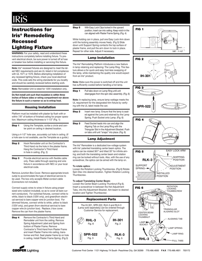
Instructions for Iris® Remodeling Recessed Lighting Fixture WARNING: For your safety, read and understand these instructions completely before installing fixture. To prevent electrical shock, be sure power is turned off at fuse or breaker box before installing or servicing this fixture. Note: Iris® recessed fixtures are designed to meet the latest NEC requirements and are UL listed in full compliance with UL 1571 or 1570. Before attempting installation of any recessed lighting fixture, check your local electrical code. This code sets the wiring standards for you locality and should be carefully reviewed before starting work. Note: Remodeler Unit is rated for 120V installation only. Do Not install unit such that insulation is within three inches of fixture sides or wiring compartment nor above the fixture in such a manner so as to entrap heat. Housing Installation Platform must be installed with plaster lip flush with or within 7/8” of bottom of finished ceiling for proper operation. Maximum ceiling thickness is 1-1/2” (Fig. 1) Step 1 Using the Template, scribe a circle and center point on ceiling in desired location. Using a 4-1/2” hole saw, accurately cut hole in ceiling. (If a hole saw is not available, use the Template as a guide.) Step 2 Step 3 Hook Remodeler unit on the Contractor’s Third Hand via the hole in the plaster frame. Hang the Contractor’s Third Hand in hole in ceiling. (Fig. 2) Provide electrical service with flexible cable only. Pass cable through opening and wire fixture in accordance with NEC or your local electrical code. Remove Junction Box Cover. Remove appropriate knock out(s) to accommodate the type of electrical service to be used. The box only accepts Metal conduit cable (Connectors not included). Connect supply wires to wires in fixture using proper sized wire nuts(not included), so as to cover all bare current conductors. For switched fixtures, connect white to white, black to black (120V only), and green(from electrical service) to bare copper wire (in junction box). For dimmed fixtures, connect white to white, yellow to black (120V only), and green (from electrical service) to bare copper wire (in junction box). Replace J-box cover. Remove the can from the plaster frame. Step 4 Remove the Contractor’s Third Hand and Remodeler unit from the ceiling. Remove Spring Adjustment Label and Spring from bottom of Plaster Frame. Remove Contractor’s Third Hand from Plaster Frame and insert Plaster Frame into ceiling, transformer end first. Seat plaster frame lip on hole in ceiling. Install Plaster Frame Spring. (Fig.3) Step 5 With Easy Lock Clips locked in the upward position, insert can into ceiling. Keep notch in the can aligned with Plaster Frame Spring. (Fig. 4) FIG 1 While holding can in place, pull one Easy Lock Arm down until the locking assembly moves freely. (Fig 5) Slide down until Support Spring contacts the top surface of plaster frame, and pull the arm down to lock in place. Repeat for other side. Adjust if necessary. Lamp Installation 5/8" - 1-1/2" FIG 2 The Iris Remodeling Platform introduces a new feature in lamp retaining and replacing: The Lamp Ring. This feature allows a for quick and easy tool-less swapping of the lamp, while maintaining the quality one would expect from an Iris® product. ® IH-301 Note: Make sure the power is switched off and the unit has sufficiently cooled before handling a hot lamp. FIG 3 Step 1 Pull tabs down on Lamp Ring until unit disengages from the spin disc assembly. (Fig. 6) Note: In replacing lamp, ensure lamp wattage meets the UL requirement for the designated trim fixture by verifying with the UL label inside the can. Step 2 Insert new lamp. Ensure that the lamp is seated against the Lens and retained by the Lamp Spring. Push Socket onto Lamp. (Fig. 6) Step 3 Feed Socket leads into can and align the Aligning Tab on the Lamp Ring with the Triangular Slot in the Adjustment Bracket. Push on tabs until unit “snaps” into place. (Fig. 6) SPR-522 FIG 4 Lamp Adjustment The Iris® Remodeler is a dedicated low-voltage system with Iris’ patented translating center beam optics. The optics can be rotated 361º and tilted 35º for infinite aiming; and both the translating center beam and rotation ring can be locked without tools. Also, with the use of any screwdriver, the optics can be aimed with the lamp on. To rotate optics: Loosen the Rotation Locking Thumbscrew. (Fig 6) Rotate Spin Disc into desired location. Tighten Rotation Locking Thumbscrew. To adjust Translating Center Beam: Loosen the Center Beam Locking Thumbnut (Fig 6). Insert a screwdriver in-between the Hot Adjustment Tabs, into the Adjustment Bracket. Aim beam to desired location and Tighten Thumbscrew EASY LOCK ARM FIG 5 SHIPPING POSITION RLK-3 SUPPORT SPRING ADJUSTMENT POSITION INSTALLED POSITION ROTATION LOCKING THUMBSCREW FIG 6 Replacement Parts The IH-301, SPR-522, RLK-3 and RLH-3 (Lamp sold seperately) can be ordered through Customer Service for replacement. CENTER BEAM LOCKING THUMBNUT RHL-3 IH-301 Fig. 6 Fig. 2 TRIANGULAR ALIGNING SLOT ALIGNING TAB LAMP SOCKET LAMP SPRING SPR-522 RLK-3 Fig. 3 Fig. 5 LAMP RING RHL-3 Customer First Center 1121 Highway 74 South Peachtree City, GA 30269 770.486.4800 PULL TABS F A X 770.486.4801 703172


