Technical data sheet
2008
MV network management - Easergy range
Flite 110-SA
Fault passage indicator
for overhead network
PE41017
Advantages
■ Flite 110-SA adjusts to the network voltage and frequency.
Using fault detectors makes it easier to locate faults on distribution networks.
The detector must adapt to the electrical network characteristics and be perfectly
visible to allow maintenance teams to quickly detect faulty network sections.
■ Flite 110-SA is configurable on site.
An overhead fault detector must be coordinated with the upstream protection system
whose trip threshold can vary according to its position on the MV network.
■ Flite 110-SA indicates permanent and transient faults with the same
indication light intensity.
A fault detector always indicates permanent faults, but utilities companies often also
want to find transient fault (a fault is considered to be “transient” when the upstream
protection device eliminates the fault during its reclosing cycle).
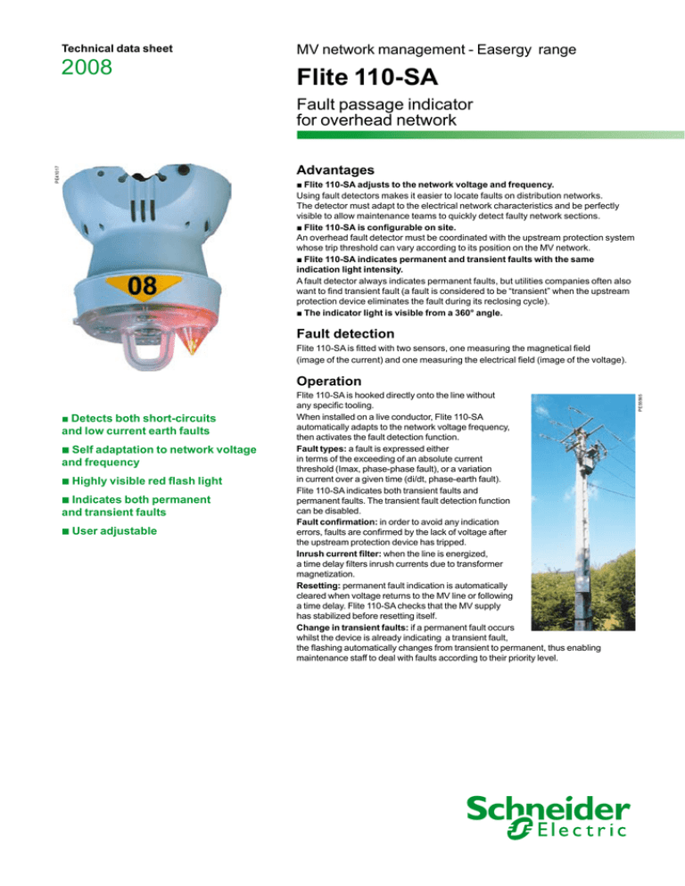
■ The indicator light is visible from a 360° angle.
Fault detection
Flite 110-SA is fitted with two sensors, one measuring the magnetical field
(image of the current) and one measuring the electrical field (image of the voltage).
■ Detects both short-circuits
and low current earth faults
b Self adaptation to network voltage
and frequency
b Highly visible red flash light
b Indicates both permanent
and transient faults
b User adjustable
Flite 110-SA is hooked directly onto the line without
any specific tooling.
When installed on a live conductor, Flite 110-SA
automatically adapts to the network voltage frequency,
then activates the fault detection function.
Fault types: a fault is expressed either
in terms of the exceeding of an absolute current
threshold (Imax, phase-phase fault), or a variation
in current over a given time (di/dt, phase-earth fault).
Flite 110-SA indicates both transient faults and
permanent faults. The transient fault detection function
can be disabled.
Fault confirmation: in order to avoid any indication
errors, faults are confirmed by the lack of voltage after
the upstream protection device has tripped.
Inrush current filter: when the line is energized,
a time delay filters inrush currents due to transformer
magnetization.
Resetting: permanent fault indication is automatically
cleared when voltage returns to the MV line or following
a time delay. Flite 110-SA checks that the MV supply
has stabilized before resetting itself.
Change in transient faults: if a permanent fault occurs
whilst the device is already indicating a transient fault,
the flashing automatically changes from transient to permanent, thus enabling
maintenance staff to deal with faults according to their priority level.
PE55565
Operation
Characteristics
Flite 110-SA
1 - Fixing the unit on the hook
2 - Pushing the unit onto
the line
PE55564
Installation tool with SICAME adapter
7 kV to 69 kV (1)
50 Hz and 60 Hz
Impedant, solidly grounded
5 to 22 mm
6-12-25-60-90-120-160 A-Off
100-200-500-800 A
On - Off
30 ms ± 10 ms
3s
U < 45% Un
Voltage drop within 70 s after fault detection
Voltage presence during 70 s
2 - 4 - 8 -16 hours
By magnet
Red flash light
40 lumens
360°
1 flash every 3 s (0 to 2 h)
2 flashes every 12 s (0 to 8 h)
800 hours
> 10 years
– 40°C to +85°C
– 40°C to + 85°C
IP 54 IK 7
130 mm x 130 mm
360 g
150 km per hour
25 kA/170 ms (ANSI 495)
125 kV/60 Hz (IEC 60060-1)
IEC 68-2-6 and 68-2-29
IEC 801-3 and FCC Part 15
IEC 68-2-11 and 68-2-30
(1) < 7 kV on request
Installation
Flite 110-SA is clipped on a live conductor:
b either with a standard shotgun hotstick,
b or with a hotstick fitted with a universal adapter and a Flite 110-SA installation tool
(see references below).
Description
Flite 110-SA
Replacement lithium battery
Installation tool with SICAME adapter
Installation tool with BOWTHORP adapter
12 meter telescopic hotstick (20 kV insulated)
Schneider Electric Industries SAS
89, boulevard Franklin Roosevelt
F-92505 Rueil-Malmaison Cedex
Tél. : +33 (0)1 41 29 85 00
www.schneider-electric.com
www.easergy.com
ENMED300023EN
References
59938
59982
59953
59954
59955
As standard, specifications and designs change from time to time, please ask for confirmation of
the information given in this publication.
This document has been
printed on ecological paper
Publishing : Schneider Electric Industries SAS
Production : Schneider Electric Industries SAS
Printing : Imprimerie du Pont de Claix/JPF - Made in France
08-2008
ART.94701 © Schneider Electric Industries SAS - All rights reserved
PE55563
PE55562
Installation with shotgun hotstick
Application
Distribution network voltage
Power frequency
MV neutral arrangement
Conductor diameter
Fault detection - parameters
di trigger setting
Imax trigger
Transient faults detection
dt value for di/dt operation
Inrush restraint duration
Loss of voltage condition
Fault confirmation
Reset (permanent faults)
Automatic power return reset
Timer reset
Manual reset
Fault indication
Indication
Light power
Visibility angle
Flash period for permanent faults
Flash period for transient faults
Standard total flash duration
Power supply
Lithium battery life expectancy
Environment
Operation temperature
Storage temperature
Protection level
Mechanical
Dimensions
Net weight
Wind resistance
Standards
Short-circuit withstand
Dielectric test
Vibrations and shocks test
EMI/EFI immunity
Salty fog and humidity tests


