Secondary Containment Pipe and Two-Piece
Fittings
Product
Name 14/15
(Red Thread™, Green Thread™, Z-Core™, Centricast Plus™ RB-2530 or CL-2030 and Centricast™ RB-1520 or CL-1520)
Product
NOV Fiber Glass Systems offers secondary containment piping systems
with two-piece fittings that meet EPA requirements and help protect
the environment by containing possible fluid leaks in case of damage
to the system. Both vinyl ester and epoxy resin systems are available to
match your application.
OIL & GAS
CHEMICAL
& INDUSTRIAL
Fittings
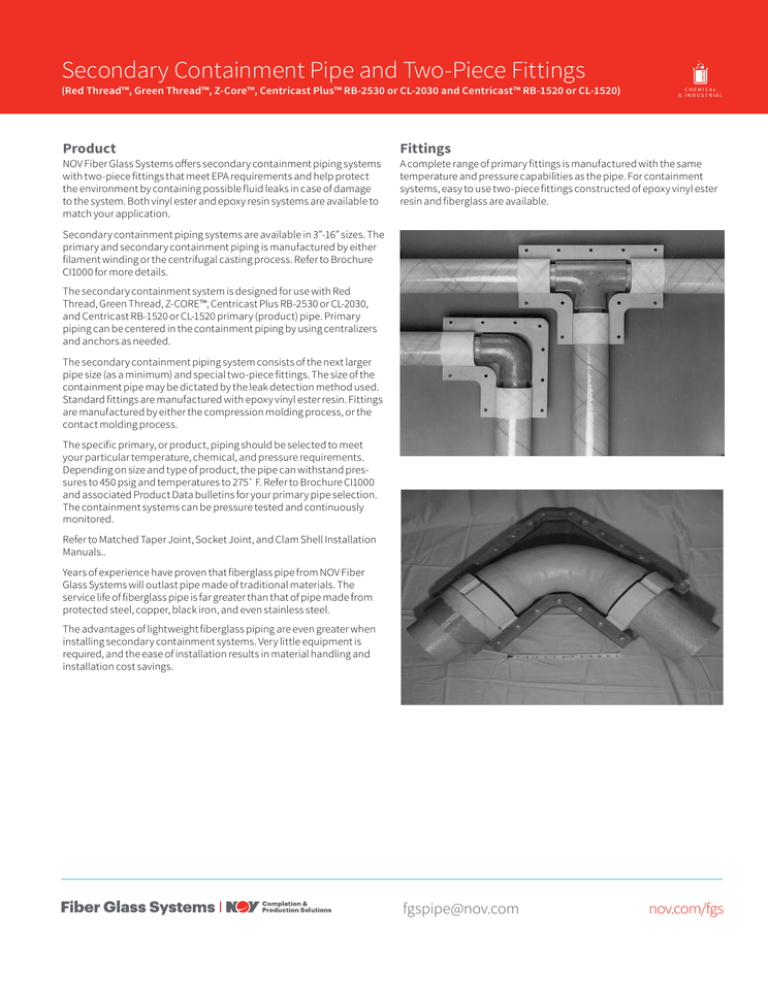
A complete range of primary fittings is manufactured with the same
temperature and pressure capabilities as the pipe. For containment
systems, easy to use two-piece fittings constructed of epoxy vinyl ester
resin and fiberglass are available.
Secondary containment piping systems are available in 3”-16” sizes. The
primary and secondary containment piping is manufactured by either
filament winding or the centrifugal casting process. Refer to Brochure
CI1000 for more details.
The secondary containment system is designed for use with Red
Thread, Green Thread, Z-CORE™, Centricast Plus RB-2530 or CL-2030,
and Centricast RB-1520 or CL-1520 primary (product) pipe. Primary
piping can be centered in the containment piping by using centralizers
and anchors as needed.
The secondary containment piping system consists of the next larger
pipe size (as a minimum) and special two-piece fittings. The size of the
containment pipe may be dictated by the leak detection method used.
Standard fittings are manufactured with epoxy vinyl ester resin. Fittings
are manufactured by either the compression molding process, or the
contact molding process.
The specific primary, or product, piping should be selected to meet
your particular temperature, chemical, and pressure requirements.
Depending on size and type of product, the pipe can withstand pressures to 450 psig and temperatures to 275˚ F. Refer to Brochure CI1000
and associated Product Data bulletins for your primary pipe selection.
The containment systems can be pressure tested and continuously
monitored.
Refer to Matched Taper Joint, Socket Joint, and Clam Shell Installation
Manuals..
Years of experience have proven that fiberglass pipe from NOV Fiber
Glass Systems will outlast pipe made of traditional materials. The
service life of fiberglass pipe is far greater than that of pipe made from
protected steel, copper, black iron, and even stainless steel.
The advantages of lightweight fiberglass piping are even greater when
installing secondary containment systems. Very little equipment is
required, and the ease of installation results in material handling and
installation cost savings.
fgspipe@nov.com
nov.com/fgs
MARINE
2
Secondary Containment Pipe and Two-Piece Fittings
Standard Secondary Containment Piping Systems
Primary Pipe Size
Minimum Containment Pipe Size for Red
Thread & Green Thread Primary Pipe
Minimum Containment Pipe Size for
Centricast RB & CL and Z-Core Primary Pipe
in
mm
in
1
--
3
1½
--
3
2
3(1)
3(1)
3
4 (1)
4 (1)
4
6 (1)
6 (1)
6
8
8
8
10
10 (2)
10
12
12
12
14
14
14
16
16
(1)
When using 2”, 3”, or 4” sweep fittings, use containment pipe and fittings that are two diameter sizes larger than the primary. Contact the factory for recommendations.
(2)
When using 8” 90º elbows, 12” containment 90º elbows may be needed. Contact factory for recommendations.
NOTE: When using 3” 90˚ elbows, 6” containment 90˚ elbow may be needed. Contact the factory for recommendations.
NOTE: Primary couplings must be installed inside of secondary containment coupling fittings.
Installation
Refer to installation manuals for instructions.
NOTE: It is highly recommended that assembly training be conducted
by a factory representative prior to installation start up.
When connecting containment pipe and fittings, plain ends of the
containment pipe are machined or thoroughly sanded to accept the
two-piece containment fitting. Containment pipe must be positioned
over the primary piping before assembly and bonding of the primary
pipe system. The size of the containment fittings may dictate the
minimum center line dimensions for the primary piping.
Upon completion of a successful primary pipe test procedure, the
two-piece secondary containment fittings may be installed. They
are installed using threaded inserts embedded in the fittings and
the hex-head bolts supplied by NOV Fiber Glass Systems. A systemmatching adhesive must be applied to all bonding surfaces just prior to
being joined by the bolts. The secondary containment system must be
given time for the adhesive to properly cure before testing the annular
space.
The testing of secondary containment piping systems is recommended
to ensure the integrity of the pipe, fittings and joints of all types. The
introduction of the test fluid during testing should be controlled to
prevent sudden pressure surges (Water Hammer). Water Hammer can
produce pressures that greatly exceed recommended system test
pressure.
WARNING: These procedures must be followed to avoid serious personal injury or
property damage. Failure to do so will result in loss of warranty. Buyer, installer or any
employee, agent or representative thereof assumes the risk of any damage or injury to
person or property.
Testing with air or gas can be extremely dangerous. Review safety precautions before
starting the test and follow all testing procedures.
Air Testing
Hydrostatic test should be used instead of air or compressed
gas if possible. When air or compressed gas is used for testing,
tremendous amounts of energy can be stored in the system. If a
failure occurs, the energy may be released catastrophically, which
can result in property damage and personal injury. In cases where
system contamination or fluid weight prevents the use of hydrostatic
test, air test may be used with extreme caution. To reduce the risk
of air testing, use the use the table below to determine maximum
pressure. When pressurizing the system with air or compressed
gas, the area surrounding the piping must be cleared of personnel
to prevent injury. Hold air pressure for one hour, then reduce the
pressure to one half the original. Personnel can then enter the area
to perform soap test of all joints. Again, extreme caution must
be exercised during air testing to prevent property damage or
personnel injury. If air or compressed gas testing is used, NOV Fiber
Glass Systems will not be responsible for any resulting injury to
personnel or damage to property, including the piping system. Air or
compressed gas testing is done entirely at the discretion and risk of
management at the job site.
Maximum Allowable Air Test Pressure
Containment Pipe Size
3"-8"
10"
12"-16"
Pressure, psig
15
10
5
Secondary Containment Pipe and Two-Piece Fittings
3
Anchors
Custom Design
Anchors are available to control pipe movement due to thermal
expansion/contractions or fluid flow transients. Secondary
containment anchors bond directly to the primary pipe and to the
inside of the secondary containment fittings to eliminate relative
movement between the two piping systems. The secondary piping
can be anchored externally by the methods in Manual No. ENG1000
as required.
NOV Fiber Glass Systems can help you in solving secondary
containment piping design problems. NOV Fiber Glass Systems also
has experience in designing and installing double-wall secondary
containment systems 16” diameter and larger. Contact NOV Fiber
Glass Systems for additional information.
Dimensional Data for Containment Fittings
Containment(2)
A
Size
B
C
D (1)
E
F
H
I
W
in
mm
in
mm
in
mm
in
mm
in
mm
in
mm
in
mm
in
mm
in
mm
in
mm
3
80
6
152
7
178
14
356
--
--
11
298
7
178
2
51
7
178
1½
38
4
100
7½
191
8
203
14
356
6
152
13
333
7
181
2
51
8
203
1½
38
6
150
8
203
9
229
16
406
8
279
15
387
8
203
2
51
9
229
1½
38
8
200
11
279
13
330
20
508
12
305
23¼
591
13
330
2½
64
14
356
1½
44
10
250
18
457
21½
546
24
610
15
381
32½
826
19
483
43/16
106
21½
546
1¾
44
12
300
21½
546
26
660
26¼
667
17
432
37½
953
22½
572
43/16
106
26
660
1¾
44
14
350
22½
572
27
686
28
711
29
737
43½
1,105 28½
724
5
127
27
686
1¾
44
16
400
22½
572
29
737
32
813
31½
800
47½
1,207 32
813
5
127
29
737
1¾
44
(1)
The overall length is based on the largest size.
(2)
Sizes 3"-6” are compression molded and 8"-16” are contact molded.
View of Fitting Illustrations
45° Elbow
Coupling
90° Elbow
Centralizers
Tee
45° Lateral
Concentric Reducer
fgspipe@nov.com
Anchor Assembly
Termination Fitting (Vented/Non Vented)
nov.com/fgs
4
National Oilwell Varco has produced this brochure for general
information only, and it is not intended for design purposes. Although
every effort has been made to maintain the accuracy and reliability of
its contents, National Oilwell Varco in no way assumes responsibility
for liability for any loss, damage or injury resulting from the use of
information and data herein nor is any warranty expressed or implied.
Always cross-reference the bulletin date with the most current version
listed at the web site noted in this literature.
Secondary Containment Pipe and Two-Piece Fittings
Fiber Glass Systems
17115 San Pedro Avenue, Ste 200
San Antonio, Texas 78232 USA
Phone: 210 477 7500
Fax: 210 477 7560
© 2016 National Oilwell Varco All rights reserved
CI1352ENG April 2016
fgspipe@nov.com
nov.com/fgs


