Chapter 30-31 Solutions
advertisement

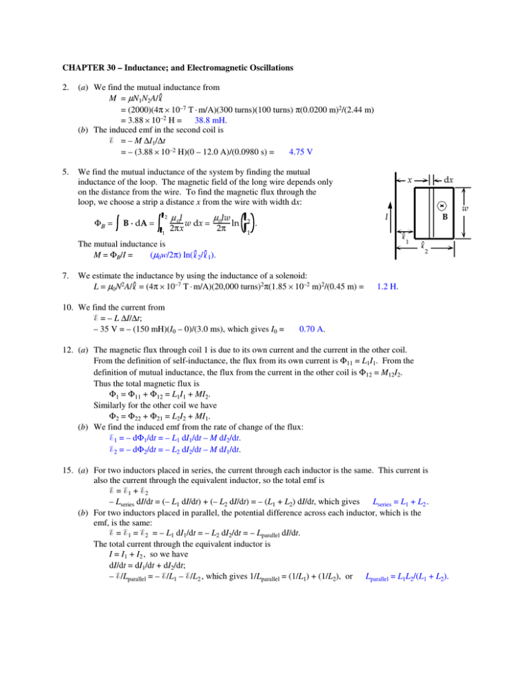
CHAPTER 30 – Inductance; and Electromagnetic Oscillations 2. (a) We find the mutual inductance from M = µN1N2A/ = (2000)(4π × 10–7 T · m/A)(300 turns)(100 turns) π(0.0200 m)2/(2.44 m) = 3.88 × 10⁻² H = 38.8 mH. (b) The induced emf in the second coil is = – M ∆I1/∆t 4.75 V = – (3.88 × 10⁻² H)(0 – 12.0 A)/(0.0980 s) = 5. We find the mutual inductance of the system by finding the mutual inductance of the loop. The magnetic field of the long wire depends only on the distance from the wire. To find the magnetic flux through the loop, we choose a strip a distance x from the wire with width dx: ΦΒ = 2 B · dA = 1 µ 0I 2πx w dx = µ0Iw 2π ln 2 x I . B 1 1 The mutual inductance is M = ΦB/I = (µ0w/2π) ln( 2/ 1). 7. dx 2 We estimate the inductance by using the inductance of a solenoid: L = µ0N2A/ = (4π × 10–7 T · m/A)(20,000 turns)2π(1.85 × 10⁻² m)2/(0.45 m) = 10. We find the current from = – L ∆I/∆t; – 35 V = – (150 mH)(I0 – 0)/(3.0 ms), which gives I0 = 1.2 H. 0.70 A. 12. (a) The magnetic flux through coil 1 is due to its own current and the current in the other coil. From the definition of self-inductance, the flux from its own current is Φ11 = L1I1. From the definition of mutual inductance, the flux from the current in the other coil is Φ12 = M12I2. Thus the total magnetic flux is Φ1 = Φ11 + Φ12 = L1I1 + MI2. Similarly for the other coil we have Φ2 = Φ22 + Φ21 = L2I2 + MI1. (b) We find the induced emf from the rate of change of the flux: 1 = – dΦ1/dt = – L1 dI1/dt – M dI2/dt. 2 = – dΦ2/dt = – L2 dI2/dt – M dI1/dt. 15. (a) For two inductors placed in series, the current through each inductor is the same. This current is also the current through the equivalent inductor, so the total emf is = 1+ 2 – Lseries dI/dt = (– L1 dI/dt) + (– L2 dI/dt) = – (L1 + L2) dI/dt, which gives Lseries = L1 + L2 . (b) For two inductors placed in parallel, the potential difference across each inductor, which is the emf, is the same: = 1 = 2 = – L1 dI1/dt = – L2 dI2/dt = – Lparallel dI/dt. The total current through the equivalent inductor is I = I1 + I2 , so we have dI/dt = dI1/dt + dI2/dt; – /Lparallel = – /L1 – /L2 , which gives 1/Lparallel = (1/L1) + (1/L2), or Lparallel = L1L2/(L1 + L2). w 19. (a) For the energy densities we have uE = 0E2 = (8.85 × 10⁻¹² F/m)(1.0 × 104 V/m)2 = 4.4 × 10⁻⁴ J/m3; 1.6 × 10⁶ J/m3. uB = B2/µ0 = (2.0 T)2/(4π × 10–7 T · m/A) = We see that uB » uE. (b) We find the magnitude of the electric field from u E = 0E 2; 1.6 × 10⁶ J/m3 = (8.85 × 10⁻¹² F/m)E2, which gives E = 6.0 × 10⁸ V/m. 21. The magnetic field at the surface of the wire is B = µ0I/2πR. The energy density of the magnetic field is uB = B2/µ0 = µ0I 2/8π2R2 = (4π × 10–7 T · m/A)(25 A)2/8π2(1.5 × 10–3 m)2 = 4.4 J/m3. If V is the potential along a length of the wire, the electric field is E = V/ = IR/ = Iρ/A = Iρ/πR2. The energy density of the electric field is uE = 0E2 = 0(Iρ/πR2)2 = (8.85 × 10⁻¹² F/m)[(25 A)(1.68 × 10⁻⁸ Ω · m)/π(1.5 × 10–3 m)2]2 = 1.6 × 10⁻¹⁴ J/m3. 28. (a) For an LR circuit, we have I = Imax(1 – e – t/τ); = 1 – e – t/τ, or – t/τ = – (2.56 ms)/τ = ln , which gives τ = 3.69 ms. (b) We find the resistance from τ = L/R; 3.69 × 10⁻³ s = (310 H)/R, which gives R = 8.39 × 10⁴ Ω = 83.9 kΩ. 30. (a) Immediately after the switch is closed, the induced emf in L R3 the inductor is maximum while the current in the inductor is zero, so we have I3 I3 = 0. 2 For loop 1, we have R2 I1 = I2 = /(R1 + R2). a (b) After a long time, the currents will be constant, and there will be no induced emf in the inductor. For the junction at point a, we have I2 I1 = I2 + I3 . 1 For loop 1, we have – I1R1 – I2R2 = 0. S For loop 2, we have + I2R2 – I3R3 = 0, or I2 = (R3/R2)I3. When we use this in the junction equation, we get I1 = [1 + (R3/R2)]I3 = [(R2 + R3)/R2]I3. From the loop 1 equation we get = [(R2 + R3)/R2]I3R1 + (R3/R2)I3R2 , which gives I3 = R2 /(R1R2 + R1R3 + R2R3). Then I1 = (R2 + R3) /(R1R2 + R1R3 + R2R3), I2 = R3 /(R1R2 + R1R3 + R2R3). (c) Immediately after the switch is opened, the current in R1 is zero, so we have I1 = 0, and the current I3 starts to decay in the LR circuit. Thus we have – I2 = I3 = R2 /(R1R2 + R1R3 + R2R3). (d) After a long time, all currents will be zero: I1 = I2 = I3 = 0. b R1 I1 å 34. (a) The resonant frequency is f0 = (1/2π)(1/LC)1/2 = (1/2π)[1/(175 × 10–3 H)(760 × 10–12 F)]1/2 = 1.38 × 10⁴ Hz = 13.8 kHz. (b) The maximum charge on the capacitor is Q0 = CV, so the peak value of the current is I0 = Q0ω = CV ω = (760 × 10–12 F)(135 V)2π(1.38 × 10⁴ Hz) = 8.90 × 10⁻³ A = 8.90 mA. (c) The maximum energy stored in the inductor is ULmax = LI02 = (175 × 10–3 H)(8.90 × 10⁻³ A)2 = 6.93 × 10⁻⁶ J. CHAPTER 31 – AC Circuits 3. 6. We find the frequency from XC = 1/2πfC; 6.70 × 10³ Ω = 1/2πf(2.40 × 10–6 F), which gives f = We find the impedance from Z = XL = ωL = 2πfL = 2π(33.3 kHz)(36.0 × 10⁻³ H) = For the rms current we have Irms = Vrms/XL = (750 V)/(7.53 kΩ) = 99.6 mA. 9.90 Hz. 7.53 kΩ. 9. (a) If the voltage is V = V0 sin ωt, the charge on the capacitor is ICmax 90° Q = CV = CV0 sin ωt. Thus the current is I = dQ/dt = ωCV0 cos ωt = ωCV0 sin ( ωt + 90°). (b) If the voltage is V = V0 sin ωt, for the circuit we have V = V0 sin ωt = L dI/dt, or dI/dt = (V0 /L) sin ωt. When we integrate this we get I = – (V0/ωL) cos ωt = (V0/ ωL) sin ( ωt – 90°). 11. Because the capacitor and resistor are in parallel, their currents are IC = V/XC , and IR = V/R. The total current is I = IC + IR . (a) The reactance of the capacitor is XC1 = 1/2πf1C = 1/2π(60 Hz)(0.35 × 10⁻⁶ F) = 7.58 × 10³ Ω = 7.58 kΩ. For the fraction of current that passes through C, we have fraction1 = IC1/(IC1 + IR) = (1/XC1)/[(1/XC1) + (1/R)] = R/(R + XC1) = (0.400 kΩ)/(0.400 kΩ + 7.58 kΩ) = 0.050 = 5.0%. (b) The reactance of the capacitor is XC2 = 1/2πf2C = 1/2π(60,000 Hz)(0.35 × 10⁻⁶ F) = 7.58 Ω. For the fraction of current that passes through C, we have fraction2 = IC2/(IC2 + IR) = (1/XC2)/[(1/XC2) + (1/R)] = R/(R + XC2) = (400 Ω)/(400 Ω + 7.58 Ω) = 0.98 = 98%. Thus most of the high-frequency current passes through the capacitor. V0 ωt 90° ILmax 15. (a) The reactance of the capacitor is XC = 1/2πfC = 1/2π(60 Hz)(0.80 × 10⁻⁶ F) = 3.32 × 10³ Ω = 3.32 kΩ. The impedance of the circuit is Z = (R2 + XC2)1/2 = [(6.0 kΩ)2 + (3.32 kΩ)2]1/2 = 6.86 kΩ. The rms current is 18 mA. Irms = Vrms/Z = (120 V)/(6.86 kΩ) = (b) We find the phase angle from cos φ = R/Z = (6.0 kΩ)/(6.86 kΩ) = 0.875. In an RC circuit, the current leads the voltage, so φ = – 29°. (c) The power dissipated is P = Irms2R = (17.5 × 10⁻³ A)2(6.0 × 10³ Ω) = 1.8 W. (d) The rms readings across the elements are VR = IrmsR = (17.5 mA)(6.0 kΩ) = 105 V; VC = IrmsXC = (17.5 mA)(3.32 kΩ) = 58 V. Note that, because the maximal voltages occur at different times, the two readings do not add to the applied voltage of 120 V. 16. (a) The reactance of the inductor is XL = 2πfL = 2π(60 Hz)(0.250 H) = 94.2 Ω. The impedance of the circuit is Z = (R2 + XL2)1/2 = [(765 Ω)2 + (94.2 Ω)2]1/2 = 770.8 Ω. The rms current is Irms = Vrms/Z = (120 V)/(770.8 Ω) = 0.156 A. (b) We find the phase angle from cos φ = R/Z = (765 Ω)/(770.8 Ω) = 0.993. In an RL circuit, the current lags the voltage, so φ = + 7.02°. (c) The power dissipated is P = Irms2R = (0.156 A)2(765 Ω) = 18.5 W. (d) The rms readings across the elements are VR = IrmsR = (0.156 A)(765 Ω) = 119 V; VL = IrmsXL = (0.156 A)(94.2 Ω) = 15 V. Note that, because the maximal voltages occur at different times, the two readings do not add to the applied voltage of 120 V.


