CE1911
LAB
SYSTEM DESIGN SPECIFICATIONS
SYSTEM DESCRIPTION
This specification describes and defines the requirements of the advanced CE1911
special purpose processor. The processor uses a set of input switches to provide values
for the nibble-sized algebraic variables X and Y. It uses switches to choose one of four
possible algebraic functions. The processor completes the chosen algebraic function as
an 8-bit calculation and produces the 8-bit result. The 8-bit result is displayed as
hexadecimal on 7-segment displays.
REQUIREMENTS
1.
2.
3.
4.
5.
The system must present power-up system reset messaging.
The system must wait for a go signal provided by the user.
The system must use values provided on toggle switches.
The system must display the output value in hexadecimal on 7-segment displays.
The system must operate from DC power or USB supplied power.
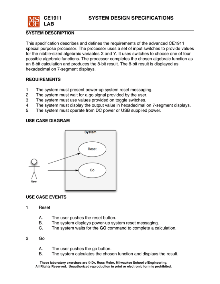
USE CASE DIAGRAM
USE CASE EVENTS
1.
Reset
A.
B.
C.
2.
The user pushes the reset button.
The system displays power-up system reset messaging.
The system waits for the GO command to complete a calculation.
Go
A.
B.
The user pushes the go button.
The system calculates the chosen function and displays the result.
These laboratory exercises are © Dr. Russ Meier, Milwaukee School ofEngineering.
All Rights Reserved. Unauthorized reproduction in print or electronic form is prohibited.
CE1911
LAB
SYSTEM DESIGN SPECIFICATIONS
SPECIFICATION OF SYSTEM INPUTS AND OUTPUTS
1.
2.
System Inputs
A.
The system uses an active-low digital signal named RST to request
system reset.
B.
The system uses an active-low digital signal named GO to request
algebra calculation.
C.
The system uses two four-bit digital signal busses to provide nibble
values for algebraic variables X and Y.
D.
The system uses a 2-bit digital signal bus to specify one of four
algebraic functions.
System Outputs
A.
3.
The system uses six 8-bit digital signal busses to display output on six 7segment displays.
Entity Input and Output Diagram
4
X
SEG75
4
Y
SEG74
2
FS
SEG73
GO
SEG72
RST
SEG71
CLK
SEG70
8
8
8
8
8
8
SPECIAL-PURPOSE PROCESSOR
These laboratory exercises are © Dr. Russ Meier, Milwaukee School ofEngineering.
All Rights Reserved. Unauthorized reproduction in print or electronic form is prohibited.
CE1911
LAB
SYSTEM DESIGN SPECIFICATIONS
SYSTEM FUNCTIONAL SPECIFICATION
A.
The system is a finite state machine controlling an arithmetic data path.
i.
ii.
iii.
iv.
B.
The machine enters the reset state when the reset pushbutton is pushed.
The machine moves through power-on reset messaging states when the
reset pushbutton is released.
The machine moves through a calculation timeline when the go
pushbutton is pushed.
The machine returns to the reset state after calculation.
Power-on reset messaging algorithm
CENTER AND DISPLAY “SPC ON” USING APPROPRIATE 7-SEG FONT
WAIT 1 SECOND
CENTER AND DISPLAY “READY” USING APPROPRIATE 7-SEG FONT
WAIT 1 SECOND
ADVANCE TO CALCULATION ALGORITHM
C.
Calculation algorithm
DO
WAIT UNTIL GO COMMAND
SWITCH(FS)
CASE 0:
CALCULATE 8X+4Y
CASE 1:
CALCULATE 5X-Y
CASE 2:
CALCULATE 12Y+6
CASE 3:
CALCULATE 2X+3Y-2
DISPLAY 8-BIT RESULT AS TWO HEX NIBBLES
FOREVER
These laboratory exercises are © Dr. Russ Meier, Milwaukee School ofEngineering.
All Rights Reserved. Unauthorized reproduction in print or electronic form is prohibited.
CE1911
LAB
D.
SYSTEM DESIGN SPECIFICATIONS
ALU Operations
i.
An ALU will be created with the following operations selected by a
control signal called ALUS.
ALUS
F(A,B,S)
0
1
2
3
4
5
6
7
F=0
F=1
F=B-1
F=A+B
F=A-B
F=A+A
F=A AND B
F=A OR B
These laboratory exercises are © Dr. Russ Meier, Milwaukee School ofEngineering.
All Rights Reserved. Unauthorized reproduction in print or electronic form is prohibited.
CE1911
LAB
SYSTEM DESIGN SPECIFICATIONS
D.
Top-level schematic: CE1911 special purpose computer (SPC) connected to
LT24 touchscreen peripheral device. A slow clock entity creates a 4Hz clock (4
clock periods per second) from LT24 output clk_50MHZ. LT24 KEY[1] is
connected to reset. LT24 pushbutton[0] is connected to GO. LT24 sliders[9..0]
provide data inputs for X, Y, and function select.
E.
Special purpose computer schematic:
NOTE: BUSMUX as a name conflicts in LT24 based projects. Use the name
MYBUSMUX instead of BUSMUX in your work!
These laboratory exercises are © Dr. Russ Meier, Milwaukee School ofEngineering.
All Rights Reserved. Unauthorized reproduction in print or electronic form is prohibited.
CE1911
LAB
SYSTEM DESIGN SPECIFICATIONS
SYSTEM IMPLEMENTATION TECHNOLOGY SPECIFICATION
1.
2.
The system is described as dataflow and behavioral VHDL architectures.
The system is implemented in an off-the-shelf Altera DE0-Nano-SOC FPGA
board.
Table 1 maps system signals to Altera DE0-Nano-SOC input and output devices.
3.
Table 1: System inputs and outputs mapped to Altera DE0 and LT24 signals
SYSTEM SIGNAL
ALTERA DE0
SYSTEM SIGNAL
ALTERA DE0
CLK
50 MHz oscillator
RST
KEY[1]
GO
pushbutton[0]
X
sliders[7..4]
Y
sliders[3..0]
FUNCSEL[1..0]
sliders[9..8]
SEG7x
SEG7x[7..0]
TEST AND VERIFICATION PLAN
1.
Simulation verifies the reset and operational use cases of a non-LT24 project.
A.
B.
C.
C.
D.
E.
2.
Simulation includes the reset use case as the first event.
Simulation overwrites arbitrary values on the X and Y data inputs.
Simulation overwrites an arbitrary value on the function select inputs.
Simulation asserts the go signal for one clock cycle to request calculation.
Visual inspection verifies the calculation result.
Simulation is repeated for all four functions.
Laboratory testing verifies the reset and operational use cases.
A.
D.
Pre-laboratory testing is completed using the Altera DE0-Nano-SOC
and LT24.
Visual verification of several values of X and Y for each function.
These laboratory exercises are © Dr. Russ Meier, Milwaukee School ofEngineering.
All Rights Reserved. Unauthorized reproduction in print or electronic form is prohibited.
CE1911
LAB
SYSTEM DESIGN SPECIFICATIONS
DELIVERABLES
1.
2.
3.
4.
Review the CE1911 pre-lab expectations outlined in the course syllabus.
Use the instructor's office hours to ask preliminary lab questions.
Test and demonstrate your work by the end of the lab period in week 10.
Submit your submission packet to the instructor when you demonstrate.
HINTS:
1.
Implement the ALU using the IEEE unsigned standard logic library. Use
a single with-select statement to assign function values to F.
with ALUS select
F <= B"00000000" when B"000",
B"00000001" when B"001",
B-1 when B”010”,
etc.
2.
The requirements specify inputs X and Y as 4-bit numbers. Yet, the schematic
shows 8-bit ALU arithmetic. The four-bit X and Y inputs can be converted to 8-bit
values inside the multiplexer:
with S select
Y <= D0 when B"00", -- all 8 ALU output bits transfer: 8-bit input to 8-bit output
B"0000"&D2 when B"10", -- zero valued upper nibble, D2 in lower nibble
B"0000"&D1 when B"01", -- zero valued upper nibble, D1 in lower nibble
B"0000"&D3 when others;
Cute, huh?! This allows you to convert your four-bit input numbers to eight-bit
output numbers when you mux them into the circuit.
4.
The hexadecimal decoder simply uses with-select to decode each 7-segment
display output. A display select bus allows you to choose what is on screen. For
example, you might choose to have DISPSEL[2..0] = 000 mean that “HELLO”
displays and DISPSEL[2..0]=101 mean that the input data nibbles are converted
and displayed as hexadecimal numbers and letters (0-F).
These laboratory exercises are © Dr. Russ Meier, Milwaukee School ofEngineering.
All Rights Reserved. Unauthorized reproduction in print or electronic form is prohibited.
CE1911
LAB
SYSTEM DESIGN SPECIFICATIONS
MILESTONES
The CE1911 professors suggest working on components in this order:
-
INITIAL STATES OF CONTROLLER
SEG7DECODER
ALU
BUSMUX
REGISTER
REST OF CONTROLLER
Week 9:
-
CONTROLLER FSM commanding power-on reset messaging.
SEG7DECODE implementing power-on reset messaging characters.
4HZ CLOCK DIVIDER
ALU VHDL WRITTEN
Week 10:
-
CONTROLLER FSM commanding each of four algebraic functions.
Complete system operational.
These laboratory exercises are © Dr. Russ Meier, Milwaukee School ofEngineering.
All Rights Reserved. Unauthorized reproduction in print or electronic form is prohibited.

