Using the Dual Modulation Inputs of the LDX-3620B
advertisement

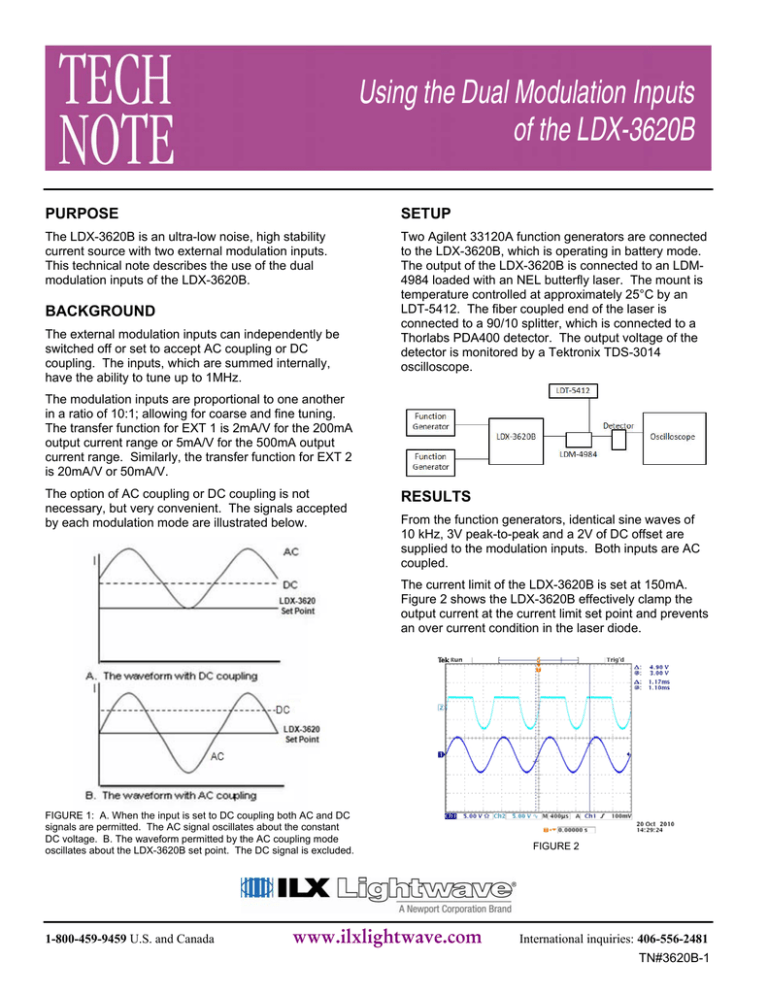
Using the Dual Modulation Inputs of the LDX-3620B PURPOSE SETUP The LDX-3620B is an ultra-low noise, high stability current source with two external modulation inputs. This technical note describes the use of the dual modulation inputs of the LDX-3620B. Two Agilent 33120A function generators are connected to the LDX-3620B, which is operating in battery mode. The output of the LDX-3620B is connected to an LDM4984 loaded with an NEL butterfly laser. The mount is temperature controlled at approximately 25°C by an LDT-5412. The fiber coupled end of the laser is connected to a 90/10 splitter, which is connected to a Thorlabs PDA400 detector. The output voltage of the detector is monitored by a Tektronix TDS-3014 oscilloscope. BACKGROUND The external modulation inputs can independently be switched off or set to accept AC coupling or DC coupling. The inputs, which are summed internally, have the ability to tune up to 1MHz. The modulation inputs are proportional to one another in a ratio of 10:1; allowing for coarse and fine tuning. The transfer function for EXT 1 is 2mA/V for the 200mA output current range or 5mA/V for the 500mA output current range. Similarly, the transfer function for EXT 2 is 20mA/V or 50mA/V. The option of AC coupling or DC coupling is not necessary, but very convenient. The signals accepted by each modulation mode are illustrated below. RESULTS From the function generators, identical sine waves of 10 kHz, 3V peak-to-peak and a 2V of DC offset are supplied to the modulation inputs. Both inputs are AC coupled. The current limit of the LDX-3620B is set at 150mA. Figure 2 shows the LDX-3620B effectively clamp the output current at the current limit set point and prevents an over current condition in the laser diode. FIGURE 1: A. When the input is set to DC coupling both AC and DC signals are permitted. The AC signal oscillates about the constant DC voltage. B. The waveform permitted by the AC coupling mode oscillates about the LDX-3620B set point. The DC signal is excluded. 1-800-459-9459 U.S. and Canada www.ilxlightwave.com FIGURE 2 International inquiries: 406-556-2481 TN#3620B-1 Using the Dual Modulation Inputs of the LDX-3620B The LDX-3620B is designed to only produce current in a single direction. Figure 3 demonstrates that the LDX3620B will not reverse bias the laser diode. Even a small reverse current can damage the laser diode. When a modulation input is turned on, but no signal is applied, there is increased noise in the current output by the LDX-3620B. FIGURE 5 FIGURE 3 A sine wave of 10 kHz frequency, 3V peak-to-peak and 2V of DC offset is supplied to EXT 2, the coarse modulation input. The input has a transfer function of 20mA/V. EXT1, the fine modulation input, is turned off. The results are demonstrated in Figure 4. SUMMARY As well as accepting two modulation signals, the results of which are shown above, the inputs will accept a modulation signal and an error feedback. The AC signal and DC feedback are supplied directly to the drive current without the complications of externally summing the error feedback to the modulation signal. The dual modulation inputs can also be used to supply a modulation signal and a DC offset from a DC voltage source to control the current. The benefit of dual modulation input is convenience in sensitive power and wavelength tuning applications. The results are higher resolution and repeatable measurements. FIGURE 4 Figure 5 shows a 10 kHz sine wave, 6V peak-to-peak and 2V of DC offset being input into EXT 1. There is nothing connected to EXT 2, but the modulation is turned on. 1-800-459-9459 U.S. and Canada www.ilxlightwave.com International inquiries: 406-556-2481 TN#3620B-1


