TRANSISTORS
THE BIPOLAR TRANSISTOR
TRANSISTORS
A transistor can be used as an amplifier
to control electric motor speed such as AC
blower motors, or as solid state switches
to control actuators such as fuel injectors.
This chapter will cover each of the
following four areas:
Transistor Operation
Transistor Applications
Transistor Gain
Integrated Circuits
Transistors are made from the same Ntype and P-type materials as diodes and
employ the same principles. Transistors,
however, have two PN junctions instead
of just one like a diode has. The two PN
junctions allow
a transistor to perform more functions
than
a diode, such as acting as a switch or an
amplifier.
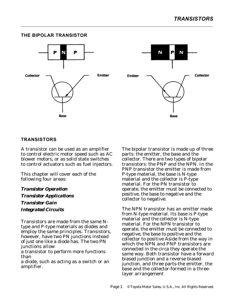
The bipolar transistor is made up of three
parts: the emitter, the base and the
collector. There are two types of bipolar
transistors: the PNP and the NPN. In the
PNP transistor the emitter is made from
P-type material, the base is N-type
material and the collector is P-type
material. For the PN transistor to
operate, the emitter must be connected to
positive, the base to negative and the
collector to negative.
The NPN transistor has an emitter made
from N-type material. Its base is P-type
material and the collector is N-type
material. For the NPN transistor to
operate, the emitter must be connected to
negative, the base to positive and the
collector to positive Aside from the way in
which the NPN and PNP transistors are
connected in the circa they operate the
same way. Both transistor have a forward
biased junction and a reverse biased
junction, and three parts-the emitter, the
base and the collector-formed in a threelayer arrangement
Page 1
© Toyota Motor Sales, U.S.A., Inc. All Rights Reserved.
TRANSISTORS
in the emitter points away from the
center so the current flow is from the base
to emitter and from the collector to
emitter.
Current flow between the emitter and
base controls the current flow between the
emitter and collector. The emitter of the
transistor is the most heavily doped so it
has the most excess electrons or holes,
depending on whether the emitter is Ptype or N-type material. The collector is
doped slightly less than the emitter and
the base is very thin with the fewest
doping atoms. As a result of this type of
doping, the current flow in the emittercollector is much greater than in the
emitter-base. By regulating the current at
the emitter-base junction, the amount of
current allowed to pass from the emitter
to the collector can be controlled.
One of the most common uses of a
transistor in an automobile is as a
switch. Switching transistors can be
found in solid state control modules and
computers. They control devices on the
car such as the fuel injector in an EFI car
or a mechanical relay that operates the
retract motor on a car with retractable
headlights. When an NPN transistor is
used as a switch, the emitter of the
transistor is grounded and the base is
connected to positive. If the voltage is
removed from the base, no current flows
from the emitter to the collector and the
transistor is off. When the base is forward
biased by a large enough voltage, current
will flow from the emitter to the collector.
Essentially, the transistor is being used to
control a large current with a small
current like a starter relay. A small
amount of current to the relay will
complete a circuit so a large current can
flow.
The symbols for both PNP and NPN
transistors are very similar. The
distinguishing feature is the arrow,
which is always located in the emitter
and always points in the direction of
conventional current flow. The base is
part of the symbol which looks like a "T"
and the remaining line, opposite the
emitter, is the collector. In the symbol for
a PNP transistor the arrow in the emitter
points toward the center so the current
flow is from emitter to base and from
emitter to collector. In the NPN transistor
the arrow
Page 2
© Toyota Motor Sales, U.S.A., Inc. All Rights Reserved.
TRANSISTORS
TRANSISTOR GAIN
We know that the current flow between
the emitter and base controls the current
flow between the emitter and collector.
Also, the amount of current flow between
the emitter and base will affect the
amount of emitter collector current. The
ratio between these two currents is
known as the "gain" of the transistor.
This gain allows us to use a transistor to
control a large current with a very small
current similar to the way a relay
operates. Example shown: if a transistor
had a gain of 100 and the emitter-base
current was increased by 10 milliamps or
.01 amps, the emitter collector current
would increase by 100 times or 1 amp.
This type of increase will occur until the
transistor reached saturation. This is the
point where increasing the emitter-base
current does not increase the emittercollector current. Transistors used for
switching usually operate at the
saturation point when turned on, while
transistors that are used for amplifiers
operate in the range between off and
saturation.
Another application for a transistor is
amplification. This situation takes
advantage of the relationship between the
emitter base current and the emittercollector current. Since a small change in
current flowing through the transistor
from the emitter to the base has a
proportionally larger effect on the
emitter-collector current, we can use
transistors to increase the strength of a
small signal in a radio or to provide a
variable control for a motor.
On some Toyota models, transistors are
being used to provide variable speed
control such as the AC blower motor on
the Cressida and the electric motor that
runs the power steering pump on the 1991
MR2. By varying the emitter-base current
of the transistor, the current flowing
through the motor can be varied, thereby
varying the motor speed.
Page 3
© Toyota Motor Sales, U.S.A., Inc. All Rights Reserved.
TRANSISTORS
ICs are classified by the number of parts
included on one chip. The Small Scale
Integration (SSI) IC has about 100
elements; the Medium Scale Integration
(MSI) IC has 100 to 1,000 elements; the
Large Scale Integration (LSI) IC has
10,000 to 100,000 elements; and the Very
Large Scale Integration (VLSI) IC has
more than 100,000 elements.
Taken with permission from the Toyota
Advanced Electrical Course#672
INTEGRATED CIRCUITS
An integrated circuit (IC) is nothing
more than many transistors, diodes,
capacitors and resistors connected
together with conductors and placed on a
single silicon chip. A single IC is a
system within a system, with several to
several thousand electrical circuits built
into or onto a several-squaremillimeter
silicon chip in a ceramic or plastic
package. The advantages of the IC are the
size and low cost of mass production
along with low power consumption and
reliability. An IC can be anything from
simple logic gate to a microprocessor to
almost a complete computer on a chip.
ICs are more reliable than nonintegrated circuits because all the
elements can be built into and onto a
single silicon chip, thereby reducing
contact junctions. In addition, the
number of components is reduced.
Page 4
© Toyota Motor Sales, U.S.A., Inc. All Rights Reserved.
TRANSISTORS
ASSIGNMENT
NAME:
1.
Describe the basic construction of a Bipolar Transistor.
2.
Draw a PNP Transistor and label its parts.
3
Explain the two current paths of a bipolar transistor.
4.
Explain the purpose of the arrow on the emitter and why is the direction of it
important.
5.
If the arrow on the emitter is pointing toward the base. What type of transistor is
it and what voltage signal (positive or negative) is needed to the base in order to
forward bias the transistor?
6.
Explain and provide an example of “transistor gain”.
7.
Describe what an integrated circuit is.


