Chapter 3 - Routledge
Chapter 3
8
Worked Example 1
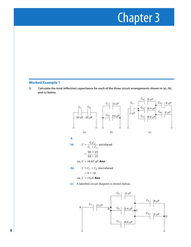
Q Calculate the total (eff ective) capacitance for each of the three circuit arrangements shown in (a), (b), and (c) below.
C
2
C
1
C
2
50 pF 25 pF
C
1
5
µ
F
C
2 10
µ
F
C
1
2
µ
F
C
3
C
4
5
µ
F
C
5
0.4
µ
F
C
6
6.6
µ
F
8
µ
2
µ
F
F
(a) (b)
A
(a) C
2
C
1
C
2
picofarad
50 25
50 25
1 6 67
(b) C C
1
C
2
microfarad
5 1 0
1 5
(c) A labelled circuit diagram is shown below.
C
2
5
µ
F
(c)
C
5 8
µ
F
A
C
1 2
µ
F
B
C
3
0.4
µ
F
C
C
6 2
µ
F
D
C
4 6.6
µ
F
Supplementary Worked Examples
C
CD
C
BC
C
5
C
6
microfarad
C
2
C
3
C
4
1 2 µ
8 2 1 0 µ F
microfarad 5 0 4
1 1 1 1
C C
AB
C
BC
30 5
60
6
C 1 .
46
µ
Ans
C
4
CD
1
6 0
1 1
2 1 2
1
1 0
Worked Example 2
Q A capacitor network connected to a d.c. supply is shown below. Calculate (a) the charge drawn from the supply, (b) the charge on C
3
, and (c) the p.d. across C
1
.
C
1 4
µ
F
C
3 8
µ
F
B C
C
2 6
µ
F
A
9
V
120 V
A
(a) C
AB
C
1
C
2
microfarad
1 0
4 6
AB
C
AC
C
AB
.
µ
3
C
3
microf
1
1
0
0
8
8
C
AC
Q VC
AC
coulomb so Q 533 µ Ans
1 20 .
1 0 6
(b) The equivalent circuit is shown below, in which each of the two eff ective capacitors will receive the same value of charge, Q coulomb, from the supply.
C
AB
C
3
B
A C
10
µ
F 8
µ
F
V
AB
V
BC
V
120 V
10
Supplementary Worked Examples
Hence the charge on C
3
533
µ
C Ans
Q
(c) From the above fi gure, V
AB volt
C
AB so, p.d. across C
1
(and C
2
) V
AB
53.3 V Ans
533 1 0
1 0 1 0 6
6
This result may be checked by calculating the p.d. across C
3
, thus:
V
BC
533 1 0
8 1 0 6
6
V
V V
AB
V
BC
53 3 .
11 which, allowing for rounding error, is 1 20 V.
Worked Example 3
Q For the circuit shown below determine (a) the p.d. V
2
, (b) the value of C
2
, and (c) the value of C
3
and the energy stored in C
3
.
C
1
C
2
C
3
10
µ
F
19.35 V V
2
48.38 V
V
100 V
A
(a) V
2
1 00 ( 1 .
.
)
1 00 .
V
2
(b) Being a series circuit, all three capacitors will receive the same value of charge from the supply; i.e. the total circuit charge Q , where
Q Q
3
Q
2
Q
1
V C coulomb
1 .
1 0 1 0 6
Q
2
C
2
1 93 5
Q
V
2 farad
1 .
1 0 6
(c)
3
W
3
W
3
C
3
C 6
µ
Ans
Q
3 farad
V
3
4
µ
Ans
1
1
2
C V 2
3 3
joule
Ans
.
0 5
1 0
4
6
1 0 6 .
2
