UG-126
EVAL_INMP401Z: Bottom Port Analog MEMS Microphone Evaluation Board
GENERAL DESCRIPTION
The EVAL_INMP401Z is a simple evaluation board that allows quick evaluation of the performance of the INMP401 bottom-ported
analog output omnidirectional microphone. The EV_INMP401 uses a 3.5 mm jack for connection to an amplifier or a sound card
input. An interconnect cable is provided with the evaluation board.
A single CR1220 3 V Lithium battery powers the INMP401. The battery is included with the board. Note that the power is always on
when the battery is inserted. Disconnect the battery when not using the evaluation board to extend battery life.
EVALUATION BOARD CIRCUIT
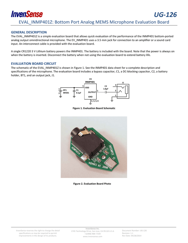
The schematic of the EVAL_INMP401Z is shown in Figure 1. See the INMP401 data sheet for a complete description and
specifications of the microphone. The evaluation board includes a bypass capacitor, C1, a DC-blocking capacitor, C2, a battery
holder, BT1, and an output jack, J1.
U1
INMP401
5
1
2
BT1
BH501
C1
0.1µF
VDD
OUTPUT
1
C2
1.0µF
GND
3
J1
2
1
2, 3, 4, 6
Figure 1. Evaluation Board Schematic
Figure 2. Evaluation Board Photo
InvenSense reserves the right to change the detail
specifications as may be required to permit
improvements in the design of its products.
InvenSense Inc.
1745 Technology Drive, San Jose, CA 95110 U.S.A
+1(408) 988–7339
www.invensense.com
Document Number: UG-126
Revision: 1.1
Rev Date: 04/28/2014
UG-126
COMPLIANCE DECLARATION DISCLAIMER
InvenSense believes the environmental and other compliance information given in this document to be correct but cannot
guarantee accuracy or completeness. Conformity documents substantiating the specifications and component characteristics are on
file. InvenSense subcontracts manufacturing and the information contained herein is based on data received from vendors and
suppliers, which has not been validated by InvenSense.
This information furnished by InvenSense is believed to be accurate and reliable. However, no responsibility is assumed by
InvenSense for its use, or for any infringements of patents or other rights of third parties that may result from its use. Specifications
are subject to change without notice. InvenSense reserves the right to make changes to this product, including its circuits and
software, in order to improve its design and/or performance, without prior notice. InvenSense makes no warranties, neither
expressed nor implied, regarding the information and specifications contained in this document. InvenSense assumes no
responsibility for any claims or damages arising from information contained in this document, or from the use of products and
services detailed therein. This includes, but is not limited to, claims or damages based on the infringement of patents, copyrights,
mask work and/or other intellectual property rights.
Certain intellectual property owned by InvenSense and described in this document is patent protected. No license is granted by
implication or otherwise under any patent or patent rights of InvenSense. This publication supersedes and replaces all information
previously supplied. Trademarks that are registered trademarks are the property of their respective companies. InvenSense sensors
should not be used or sold in the development, storage, production or utilization of any conventional or mass-destructive weapons
or for any other weapons or life threatening applications, as well as in any other life critical applications such as medical equipment,
transportation, aerospace and nuclear instruments, undersea equipment, power plant equipment, disaster prevention and crime
prevention equipment.
©2014 InvenSense, Inc. All rights reserved. InvenSense, MotionTracking, MotionProcessing, MotionProcessor, MotionFusion,
MotionApps, DMP, and the InvenSense logo are trademarks of InvenSense, Inc. Other company and product names may be
trademarks of the respective companies with which they are associated.
©2014 InvenSense, Inc. All rights reserved.
Document Number: UG-126--00
Revision: 1.1
Rev Date: 04/28/2014
Page 2 of 2


