Technical information
Notes on equipment protection per EN/IEC 60529 and NEMA
For Bourdon tube or diaphragm pressure gauges
WIKA data sheet IN 00.18
General information
This technical information describes the measures to prevent
both the formation of condensation within a hermetically
sealed case, and also the intrusion of water into cases
vented to the atmosphere. It applies for both Bourdon tube
pressure gauges and diaphragm pressure gauges.
1. Introduction and explanation of physical conditions
The formation of condensation in the cases of hermetically sealed, unfilled instruments cannot generally be avoided. This
is based on the physical fact that the humidity found in air,
In addition, water in the form of splash, jet and rain water
under particular conditions, settles on cold surfaces as
from outside can intrude into the case, so long as the instrucondensation. The warmer the air, the more humidity it can
ment is vented to atmosphere.
hold. If the air cools (e.g. at the window of a gauge), then
the air can only hold a small amount of humidity. The excess
humidity settles as condensation on the window.
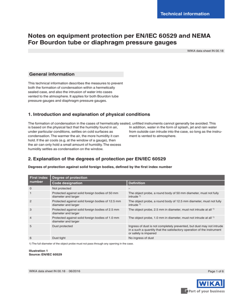
2. Explanation of the degrees of protection per EN/IEC 60529
Degrees of protection against solid foreign bodies, defined by the first index number
First index
number
Degree of protection
0
Not protected
1
2
3
4
5
6
Code designation
Definition
Protected against solid foreign bodies of 50 mm
diameter and larger
The object probe, a round body of 50 mm diameter, must not fully
intrude 1)
Protected against solid foreign bodies of 12.5 mm
diameter and larger
Protected against solid foreign bodies of 2.5 mm
diameter and larger
–
The object probe, a round body of 12.5 mm diameter, must not fully
intrude 1)
The object probe, 2.5 mm in diameter, must not intrude at all 1)
Protected against solid foreign bodies of 1.0 mm
diameter and larger
The object probe, 1.0 mm in diameter, must not intrude at all 1)
Dust tight
No ingress of dust
Dust protected
Ingress of dust is not completely prevented, but dust may not intrude
in a such a quantity that the satisfactory operation of the instrument
or safety is impaired
1) The full diameter of the object probe must not pass through any opening in the case.
Illustration 1
Source: EN/IEC 60529
WIKA data sheet IN 00.18 ∙ 06/2016
Page 1 of 6
Degrees of protection against water, defined by the second index number
Second
Degree of protection
index num- Code designation
ber
Definition
1
Perpendicularly falling drops must have no damaging effects
0
Not protected
–
2
Protected against dripping water when the case is
inclined to 15°
Perpendicularly falling drops must have no damaging effects, when
the case is inclined to an angle of up to 15°, either side of perpendicular
Protected against dripping water
3
Protected against sprayed water
4
Protected against splash water
5
Protected against water jets
6
Protected against strong water jets
7
Protected against the effects of temporary immersion
in water
8
Protected against the effects of permanent immersion
in water
Illustration 2
Water that is sprayed at an angle of up to 60°, either side of perpendicular, must have no damaging effects
Water that splashes against the case from any direction must have
no damaging effects
Water that splashes against the case, as a jet, from any direction,
must have no damaging effects
Water that splashes against the case, as a strong jet, from any
direction, must have no damaging effects
Water must not enter in any quantity which could cause damage,
when the case, under standardised pressure and temperature
conditions, is temporarily immersed in water
Water must not enter in any quantity which could cause damage,
when the case is permanently immersed in water, under conditions
which must be agreed between the manufacturer and user. The
conditions must, however, be more demanding than those for the
index number 7
Source: EN/IEC 60529
Example: Ingress protection IP65
■■ First index number 6:
■■ Second index number 5:
Dust tight, no ingress of dust
Protected against water jets: Water that splashes against the case as a jet from any direction
must have no damaging effects.
3. Comparison of NEMA (National Electrical Manufacturers Association) and
EN/IEC 60529
NEMA ingress protection
Model number
EN/IEC 60529 ingress
protection
Classification
1
IP10
2
IP11
3
IP54
3R
IP14
3S
IP54
4 and 4 X
IP66
5
IP52
6 and 6 P
IP67
12 and 12 K
IP52
13
IP54
Illustration 3
Page 2 of 6
WIKA data sheet IN 00.18 ∙ 06/2016
4. Measures against the formation of condensation
Different filling liquids depending on the ambient temperature and the electrical conductivity
In order to avoid the formation of condensation in the case,
WIKA recommends filling the instruments with glycerine.
For contact gauges, the filling can be made with silicone oil,
since silicone oil, unlike glycerine, is not hygroscopic and
therefore prevents a short circuit within the instrument.
If the ambient temperature drops below -20 °C, then we
recommend that the instrument absolutely must be filled with
silicone oil. Even at temperatures down to -50 °C, silicone oil
can still be used due to its low viscosity.
For flammable and/or explosive media, e.g. oxygen, inert
filling liquids must be used.
5. Hermetically sealed instruments and effects associated with them
In order to prevent the intrusion of water into the case, it is
recommended that an ingress protection method is chosen
that reliably inhibits this (see illustrations 1 and 2). The
ingress protection demands that the instrument is hermetically sealed.
With vented instruments, the vent valve has to be closed
in order to achieve the specified ingress protection.
This, however, produces a temperature error, which can
affect the measuring result (see illustrations 4, 5 and 6).
Therefore the vent valve has to be opened for a short time
before reading the measured value.
5.1 Temperature errors for unfilled and filled Bourdon tube pressure gauges
A standard 232.50/30 instrument with a pressure range greater than 25 bar can be made hermetically sealed without any
problems, and manufactured with an ingress protection of IP66. The temperature error that occurs with these instruments is
negligible, since it is so small in relation to the pressure range, that the instrument still will operate within its specified class
accuracy.
Instruments with a scale range of less than 25 bar can likewise be made hermetically sealed, though a temperature error will
then be present (see illustration 4). The temperature errors present are shown in the following graphs.
Influence in %
Temperature errors in hermetically sealed, unfilled Bourdon tube pressure gauges
Illustration 4
WIKA data sheet IN 00.18 ∙ 06/2016
Adjusted at 20 °C
Temperature in °C
Page 3 of 6
Temperature errors in hermetically sealed, filled Bourdon tube pressure gauges
Influence in %
Filled to 90 % with glycerine
Illustration 5
Temperature in °C
Influence in %
Filled to 90 % with silicone oil
Illustration 6
Page 4 of 6
Temperature in °C
WIKA data sheet IN 00.18 ∙ 06/2016
5.2 Temperature error with unfilled and filled diaphragm pressure gauges
With model 4, 5 and 7 hermetically sealed diaphragm
pressure gauges, the temperature error for scale ranges
≥ 100 mbar is negligible. For scale ranges < 100 mbar we
recommend only using instruments with a pressure compensation diaphragm.
For instrument models 73x.14, 702.01/02/03, 700.01/02
and 7x2.15, due to their mechanical design, there are no
additional temperature errors.
5.3 Model overview
Pressure gauges for which the formation of condensation and the ingress of water from the outside can be
prevented:
Influence
Formation of
condensation
Hermetically
sealed 1)
Bourdon tube pressure gauges
Model 232.50
Model 232.30
Model 233.50
filled
Model 233.30
filled
≥ 25
bar
≥ 25
bar
< 25
bar
unavoidable
Influence
negligible
For
influence
see
illustration
4
Influence
negligible
< 25
bar
For
influence
see
illustration
5 or 6
Diaphragm pressure gauges
Model 4 and 7
Model
233.30
filled, with
pressure
compensation
diaphragm
all pressure > 100 < 100
ranges
mbar
mbar
unavoidable
Influence
negligible
Technically
not
solvable
Model 4 and 7
filled
Model 4 and
7 with pressure compensation
diaphragm
> 100
mbar
all pressure
ranges
Influence
negligible
< 100
mbar
Technically
not
solvable
unavoidable
Model 4
and 7
filled, with
pressure
compensation diaphragm
all pressure
ranges
1) Hermetically sealed = airtight case
Illustration 7
6. Pressure compensation diaphragm
As can be seen in illustration 7, formation of condensation
in filled pressure gauges can be prevented by the use of
pressure compensation diaphragms, without any temperature error. Pressure compensation diaphragms can be used
for all safety pressure gauges per EN 837-1 S3.
Plastic diaphragm
Illustration 8: Rear wall of case with pressure compensation diaphragm, nominal size 63
WIKA data sheet IN 00.18 ∙ 06/2016
Illustration 9: Rear wall of case with pressure compensation diaphragm, nominal size 100
Page 5 of 6
Plastic diaphragm
Illustration 10: Rear wall of case with pressure compensation diaphragm for contact gauges,
nominal size 160
Blow-out rear wall with
pressure compensation
diaphragm
Socket
Pressure element
Connection shank
Case with solid
baffle wall
Movement with
interchangeable movement
retainer
Window
Laminated safety glass
Dial
Pointer
Sealing
Bayonet ring
Illustration 11: Exploded view drawing
Page 6 of 6
WIKA data sheet IN 00.18 ∙ 06/2016
WIKA Alexander Wiegand SE & Co. KG
Alexander-Wiegand-Straße 30
63911 Klingenberg/Germany
Tel.
+49 9372 132-0
Fax
+49 9372 132-406
info@wika.de
www.wika.de
06/2016 EN
© 09/2010 WIKA Alexander Wiegand SE & Co. KG, all rights reserved.
The specifications given in this document represent the state of engineering at the time of publishing.
We reserve the right to make modifications to the specifications and materials.


