750203M NC Instr J-Box Kit UVFRC 36-42(2).indd
advertisement
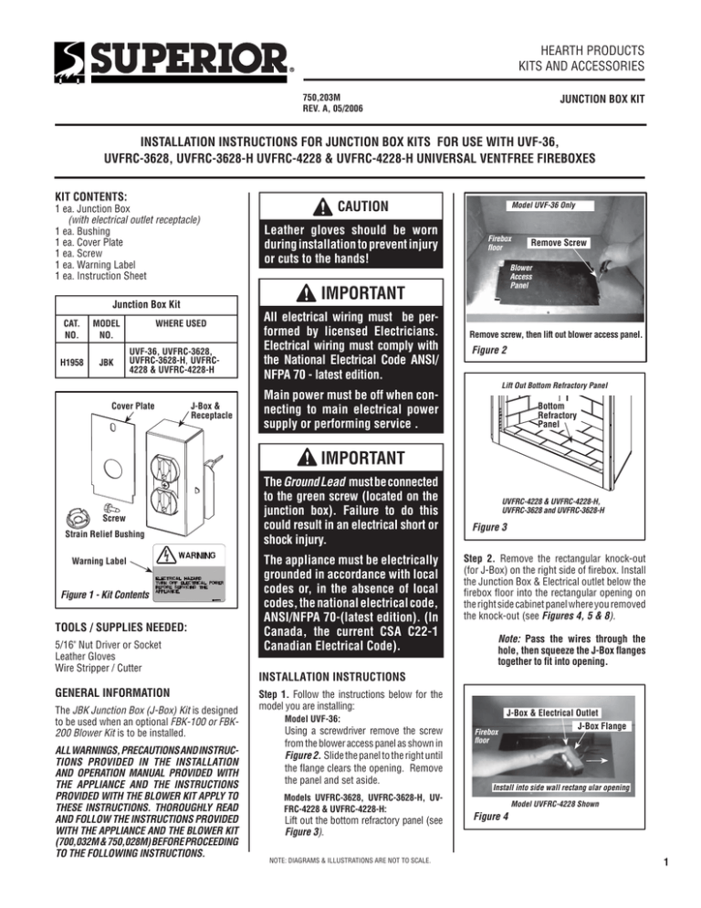
HEARTH PRODUCTS KITS AND ACCESSORIES 750,203M REV. A, 05/2006 JUNCTION BOX KIT INSTALLATION INSTRUCTIONS FOR JUNCTION BOX KITS FOR USE WITH UVF-36, UVFRC-3628, UVFRC-3628-H UVFRC-4228 & UVFRC-4228-H UNIVERSAL VENTFREE FIREBOXES KIT CONTENTS: 1 ea. Junction Box (with electrical outlet receptacle) 1 ea. Bushing 1 ea. Cover Plate 1 ea. Screw 1 ea. Warning Label 1 ea. Instruction Sheet MODEL NO. H1958 JBK Leather gloves should be worn during installation to prevent injury or cuts to the hands! Model UVF-36 Only Firebox floor WHERE USED UVF-36, UVFRC-3628, UVFRC-3628-H, UVFRC4228 & UVFRC-4228-H All electrical wiring must be performed by licensed Electricians. Electrical wiring must comply with the National Electrical Code ANSI/ NFPA 70 - latest edition. Remove Screw Blower Access Panel IMPORTANT Junction Box Kit CAT. NO. CAUTION Remove screw, then lift out blower access panel. Figure 2 Lift Out Bottom Refractory Panel Cover Plate J-Box & Receptacle Main power must be off when connecting to main electrical power supply or performing service . Bottom Refractory Panel IMPORTANT Screw Strain Relief Bushing Warning Label Figure 1 - Kit Contents TOOLS / SUPPLIES NEEDED: 5/16" Nut Driver or Socket Leather Gloves Wire Stripper / Cutter GENERAL INFORMATION The JBK Junction Box (J-Box) Kit is designed to be used when an optional FBK-100 or FBK200 Blower Kit is to be installed. ALL WARNINGS, PRECAUTIONS AND INSTRUCTIONS PROVIDED IN THE INSTALLATION AND OPERATION MANUAL PROVIDED WITH THE APPLIANCE AND THE INSTRUCTIONS PROVIDED WITH THE BLOWER KIT APPLY TO THESE INSTRUCTIONS. THOROUGHLY READ AND FOLLOW THE INSTRUCTIONS PROVIDED WITH THE APPLIANCE AND THE BLOWER KIT (700,032M & 750,028M) BEFORE PROCEEDING TO THE FOLLOWING INSTRUCTIONS. The Ground Lead must be connected to the green screw (located on the junction box). Failure to do this could result in an electrical short or shock injury. The appliance must be electrically grounded in accordance with local codes or, in the absence of local codes, the national electrical code, ANSI/NFPA 70-(latest edition). (In Canada, the current CSA C22-1 Canadian Electrical Code). UVFRC-4228 & UVFRC-4228-H, UVFRC-3628 and UVFRC-3628-H Figure 3 Step 2. Remove the rectangular knock-out (for J-Box) on the right side of firebox. Install the Junction Box & Electrical outlet below the firebox floor into the rectangular opening on the right side cabinet panel where you removed the knock-out (see Figures 4, 5 & 8). Note: Pass the wires through the hole, then squeeze the J-Box flanges together to fit into opening. INSTALLATION INSTRUCTIONS Step 1. Follow the instructions below for the model you are installing: Model UVF-36: Using a screwdriver remove the screw from the blower access panel as shown in Figure 2. Slide the panel to the right until the flange clears the opening. Remove the panel and set aside. Models UVFRC-3628, UVFRC-3628-H, UVFRC-4228 & UVFRC-4228-H: Lift out the bottom refractory panel (see Figure 3). NOTE: DIAGRAMS & ILLUSTRATIONS ARE NOT TO SCALE. Firebox floor J-Box & Electrical Outlet J-Box Flange Install into side wall rectang ular opening Model UVFRC-4228 Shown Figure 4 1 J-Box Flanges Right Outside Cabinet Panel J-Box & Electrical Outlet Wires Feed the *Romex wires (or other equivalent plastic insulated wire - Refer ANSI/NFPA 70 - National Electrical Code - Latest Edition) through the J-Box Cover retangular opening, then connect to the J-box wires. The strain relief bushing should be pressed into the knock-out on the J-box cover around the Romex (this will provide protection to the wires and prevents strain against connections from J-box). See Wiring Diagram - Figure 9. Install the cover plate over the J-Box opening on appliance as shown in Figure 7. Junction Box Blower Warning Label - Apply on bottom of the cabinet in front of blower. Top View of Firebox Figure 8 * Romex is a plastic insulated wire from power supply - sometimes called non-metallic sheath. Figure 5 Step 3. Route a 3-wire, 120 VAC, 60 Hz, 1 ph power supply to the right side of appliance per the instructions provided in blower kit and the installation & operation manual and per National Electrical Code ANSI/ NFPA 70 - latest edition. (strain relief bushing presses into this hole around romex wires - see Step 5). * Wall-mounted ON/ OFF Blower Switch or Variable Speed Control Switch. J-Box opening on appliance HOT SIDE OF RECEPTACLE Cover Plate Remove knock-out 120V, 60HZ, 1PH BLOWER CONTROL CIRCUIT WIRING Right Side Panel of Firebox Step 4. Locate the J-Box cover (provided). Remove the round knock-out (see Figure 6). Cover Plate 120 VAC Black Ground - Green Neutral - White Note: Wire connections should be positioned inside of the appliance. Screw Black The notched side of cover plates goes inside firebox panel NEUTRAL SIDE OF RECEPTACLE Use screw provided and secure in place as shown Figure 7 - Installing J-box Cover Plate - All Models Tab Intact Junction Box Plug blower into this receptacle Step 6. Apply the Warning Label provided to the bottom of the cabinet as shown in Figure 8. Green Ground Screw Field Wired Figure 6 - Junction Box Cover Plate Step 5. Ensure that power supply wires are NOT "live" before making these connections). Install J-Box Cover Plate as follows: Step 7. After the electical connections and blower installation have been completed per the instructions provided with kit and in the installation and operation manual follow the instructions below for the model you are installing: Model UVF-36 : Reinstall the blower access panel that was removed on Step 1 (see Figure 2). Models UVFRC-3628 and UVFRC-3628-H, UVFRC4228 & UVFRC-4228-H: Reinstall the bottom refractory panel that was removed on Step 1 (see Figure 3). Factory Wired Blower Ground *An ON/OFF Wall Switch is used with the FBK-100 kit (field provided or sold separately - order P/N 85L87); A Variable Speed Control (provided) is used with the FBK200 kit. The installation of these kits also require a Junction Box / Electrical Kit, not included. See Page 13 for ordering information. Note: If any of the original wire as supplied must be replaced, it must be replaced with type AWM 105 degree C - 14 gage wire. Figure 9 NOTE: DIAGRAMS & ILLUSTRATIONS ARE NOT TO SCALE. LHP reserves the right to make changes at any time, without notice, in design, materials, specifications, prices and the discontinuance of colors, styles and products. Consult your local distributor for fireplace code information. LHP Printed in U.S.A. © 2006 by LHP 2 P/N 750,203M REV. A 05/2006 1110 West Taft Avenue Orange, CA 92865
