Installation Instructions
Bulletin 1609 Industrial Uninterruptible Power Supply
(Cat 1609-B)
ATTENTION: Please read and save these instructions. This manual contains important instructions for the Bulletin 1609 Uninterruptible Power Supply. Follow these instructions during the unpacking, installation and maintenance of the UPS. If you have a problem
with the UPS, please refer to this manual and the User Manual trouble shooting section before calling Technical Services.
Contents for UPS Include:
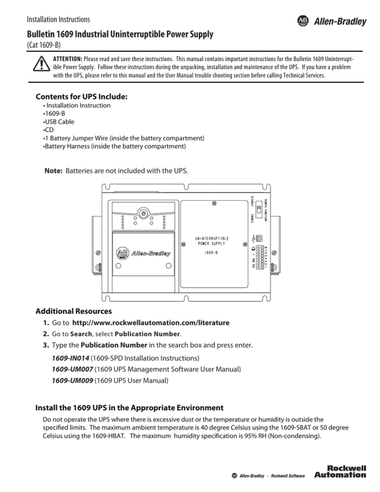
• Installation Instruction
•1609-B
•USB Cable
•CD
•1 Battery Jumper Wire (inside the battery compartment)
•Battery Harness (inside the battery compartment)
Note: Batteries are not included with the UPS.
Additional Resources
1. Go to http://www.rockwellautomation.com/literature
2. Go to Search, select Publication Number.
3. Type the Publication Number in the search box and press enter.
1609-IN014 (1609-SPD Installation Instructions)
1609-UM007 (1609 UPS Management Software User Manual)
1609-UM009 (1609 UPS User Manual)
Install the 1609 UPS in the Appropriate Environment
Do not operate the UPS where there is excessive dust or the temperature or humidity is outside the
specified limits. The maximum ambient temperature is 40 degree Celsius using the 1609-SBAT or 50 degree
Celsius using the 1609-HBAT. The maximum humidity specification is 95% RH (Non-condensing).
2
Bulletin 1609 Industrial Uninterruptible Power Supply
Batteries Wiring and Installation Instruction for the UPS
Only use battery wires that have been provided with the UPS.
Warning: Do not service the 1609-SPD without disconnecting the power sources due to electric shock harzard for risk of
severe injury or death.
1. To access the battery compartment
remove the three screws and the
battery door.
2. Remove the battery container, jumper and wire harness
from the battery compartment. Place the battery
container and batteries onto a flat surface. Use the
provided jumper wire to connect the batteries in series.
Connect the positive terminal (red) of the battery to the
negative terminal (black) of another battery. Connect
the red wire of the harness to the positive terminal (top
red) and the black wire of the harness to the negative
terminal (bottom black). See photo below for details.
Black
Red
Red
Black
Notch
End
3. Fold the battery container and seal it with tape.
4. To connect the batteries to the UPS, insert the batteries into the battery compartment, open the white
connector retainer and connect the two cables together as shown in the photo below.
Publication 1609-IN013B-EN-P - August 2012
DIR 10000234490 (Version 01)
Bulletin 1609 Industrial Uninterruptible Power Supply
Batteries Wiring and Installation Instruction for the UPS (Cont’d)
5. To complete the battery installation, close the white connector retainer and reattach the battery door with
the three screws (torque of 8.7+/-1.7 lb-in).
Mount the UPS
The 1609-B products are designed to mount to heavy duty DIN-rail (see Diagram 1 below). The 1609-B
products are also designed with an option bracket assembly (1609-BRK) that allows it to mount to either
the panel or floor (see Diagram 2 below).
Diagram 1 - Standard DIN-Rail Mount
Diagram 2 - Optional Panel or Floor Mount
Publication 1609-IN013B-EN-P - August 2012
DIR 10000234490 (Version 01)
3
4
Bulletin 1609 Industrial Uninterruptible Power Supply
Hardwire UPS
Wiring of the UPS should be performed by a qualified electrician using the appropriate wire gauges.
Selection of Cables:
AC Main Input / Output Wiring for UPS:
Item
Wire size
Minimum temperature
Wire conductor material
Tightening torque for terminals
Specification
14 AWG
75°C
Copper only
4.4 lb-in
Warning: To reduce the risk of fire, connect only to a circuit provided with 20 amperes maximum branch circuit overcurrent
protection in accordance with the National Electric Code, ANSI/NFPA 70.
A disconnect switch shall be provided by others for AC output circuit. To reduce the risk of fire, connect only to a circuit
provided with branch circuit overcurrent protection for 20 amperes rating in accordance with the National Electric Code,
ANSI/NFPA 70.
Connect Power and Equipment to the UPS
Warning: This UPS features Surge Protective Device (SPD) located on the top of the unit. Please disconnect all power
sources before servicing due to Electric Shock Hazard for risk of severe injury or death.'
1. Connect the appropriate input power to the UPS's input (Line, Neutral and Ground) terminals (see
Diagram 3).
2. Connect the specified equipment to the UPS's output (Line, Neutral and Ground) terminals (see
Diagram 3).
Diagram 3 - System Wiring
L
INPUT
N G
L
OUTPUT
N G
AC Input
AC Output
Publication 1609-IN013B-EN-P - August 2012
DIR 10000234490 (Version 01)
Bulletin 1609 Industrial Uninterruptible Power Supply
Service Instructions
a) Servicing of batteries should be performed or supervised by personnel knowledgeable of
batteries and the required precautions. Keep unauthorized personnel away from the batteries.
b) When replacing batteries, replace with the same number of the 1609 battery packs supplied by
Rockwell Automation.
Warning: Do not dispose of battery or batteries in a fire. The battery may explode. Do not open or mutilate the battery or
batteries. Released electrolyte is harmful to the skin and eyes. It may be toxic. A battery can present a risk of electrical
shock and high short circuit current.
The following precautions should be observed when working on batteries:
1)
2)
3)
4)
Remove watches, rings, or other metal objects.
Use tools with insulated handles.
Do not lay tools or metal parts on top of batteries.
Determine if battery is inadvertently grounded. If inadvertently grounded, remove source
from ground. Contact with any part of a grounded battery can result in electrical shock. The
likelihood of such shock can be reduced if such grounds are removed during installation and
maintenance.
Recommended Battery for use with the UPS
Rockwell Automation battery catalog numbers 1609-SBAT and 1609-HBAT consists of the battery
manufacturers listed below:
Manufacturer
B & B Battery (USA) INC. (MH19884)
GS Yuasa International Ltd. (MH12970)
Shenzhen Center Power Tech. Co., Ltd. (MH25860)
Shenzhen Ritar Power Co., Ltd. (MH28539)
CSB Battery Co., Ltd. (MH14533)
Type
HRL5.5 - 12
BP 5-12
HR5.5 - 12
SHR7 - 12
NPH5 - 12
CP1250
RT1250
HR1221W
Rating
12 Vdc,
12 Vdc,
12 Vdc,
12 Vdc,
12 Vdc,
12 Vdc,
12 Vdc,
12 Vdc,
2.75 Ah
5.0 Ah
2.75 Ah
3.375 Ah
5.0 Ah
5.0 Ah
5.0 Ah
5.25 Ah
Not for use in a computer room as defined in the Standard for the Protection of Electronic
Computer/Data Processing Equipment, ANSI/NFPA 75.
Dispose of used batteries according to the battery instructions.
Publication 1609-IN013B-EN-P - August 2012
DIR 10000234490 (Version 01)
5
6
Bulletin 1609 Industrial Uninterruptible Power Supply
Dry I/O Contacts
There is one Remote Enable/Disable Switch connection and 3 Dry I/O Contacts available on the front of the
UPS. Do not apply external power to the Remote Enable/Disable Switch; however, the 3 sets of Dry Contacts
required external power supplies (Contacts Rating is 1A/24 Vdc). Each of the Dry Contacts is used to provide a
remote status indication of the UPS as follows:
8 7 6 5 4 3 2 1
1 and 2 On Battery Contact (NO)
3 and 4 Low Battery Contact (NO)
5 and 6 Fault
(Indicates UPS has faulted see the User Manual trouble
shooting section)
7 and 8 Remote Enable/Disable
(Closed for Output Enable, Open for Output Disable)
USB Communication Port
The UPS supports a USB communication port for the end user to connect with a computer. The
user may monitor all the UPS status through the USB port if the 1609 UPS Management
Software is installed in the computer. The software is stored in the CD and can be found in the
accessory bag.
Manual or Remote Enable / Disable of UPS Output Selection
The 1609-B UPS output is designed to be manually or remotely Enabled or Disabled. User is required to
enable or disable the remote function switch on the front panel.
REMOTE FUNCTION
Selected 'DISABLE' for Manual Enable/Disable the UPS's Output.
Selected 'ENABLE' for Remote Enable/Disable the UPS's Output.
DISABLE
ENABLE
Manual Enable/Disable/Self-test
The Power Button on the front of the UPS is used to manually enable or disable the output of the 1609-B UPS.
To enable the 1609-B UPS, press and hold the Power Button until one beep is
heard.
To disable the 1609-B UPS, press and hold the Power Button until three beeps
are heard then release immediately (takes approximately 3 seconds).
To perform a self-test, press and hold the Power Button until two beeps are
heard then release immediately.
Publication 1609-IN013B-EN-P - August 2012
DIR 10000234490 (Version 01)
Bulletin 1609 Industrial Uninterruptible Power Supply
Remote Enable/Disable
An external switch connected to the Dry I/O terminals 7 and 8 is required to remotely Enable or Disable the
UPS output.
8 7 6 5 4 3 2 1
To enable the UPS, close the switch that is connected to the
Dry I/O terminals 7 and 8.
To Disable the UPS, open the switch that is connected to the
Dry I/O terminals 7 and 8.
R
R
R
SW
24 Vdc
Display LED indicators
Indicator
LED
Indicator Title
On-Line
Description
The UPS is supplying utility power to the connected equipment
(see the User Manual trouble shooting section).
The UPS is supplying battery power to the connected equipment.
On Battery
Overload
The connected equipment is drawing more than the UPS power
rating allows (see the User Manual trouble shooting section).
Replace Battery / Battery
Disconnected
The battery is disconnected or must be replaced
(see the User Manual trouble shooting section).
Block Diagram
Input
Filter
L
AC
Input E
Backfeed
Relay
L
E
Backfeed
Relay
N
N
Inverter
Relay
+
AC to DC (Charger)
DC to DC
Publication 1609-IN013B-EN-P - August 2012
DC to AC (Step Wave)
DIR 10000234490 (Version 01)
AC
Output
7
Service
ATTENTION: Always disconnect the battery(s) before shipping in compliance with U.S. Department of Transportation (DOT)
and IATA regulations. The battery(s) may remain in the UPS.
If the UPS requires service do not return it to the dealer. Follow these steps:
1. Review the problems discussed in the trouble shooting section of the 1609 UPS User Manual to
eliminate common problems.
2. If the problem persists, contact Rockwell Automation Customer Support at 440-646-5800.
3. Pack the UPS in its original packaging.
. Pack the UPS properly to avoid damage in transit. Never use Styrofoam beads for packaging.
. Damage sustained in transit is not covered under warranty.
Allen-Bradley, Rockwell Software, and Rockwell Automation are trademarks of Rockwell Automation, Inc.
Trademarks not belonging to Rockwell Automation are property of their respective companies.
Publication 1609-IN013B-EN-P - August 2012
DIR 10000234490 (Version 01)
Copyright © 2012 Rockwell Automation, Inc. All Rights Reserved. Printed in China.


