Phys 223, Labatorial 4, Winter 2016
University of Calgary
Department of Physics and Astronomy
PHYS 223, Winter 2016
Labatorial 4: Introduction to Electric Circuits
Goals:
To understand the electrical properties of different circuits with a power supply and 1-3 light bulbs.
Overview:
In this labatorial, you will explore how current and voltage in a circuit depend on the elements in it, and
on how those elements are connected. You will investigate the circuits theoretically, using Kirchhoff’s laws,
and you will build the circuits and measure current and voltage.
Preparation:
Randall D. Knight, Physics for Scientists and Engineers, Third Edition, Pearson/Addison-Wesley: Sections
31.1-2, 31.4, 31.6.
Equipment:
2 light bulbs, switch, Anatek power supply, connecting leads, Fluke multimeter.
Circuits and schematics
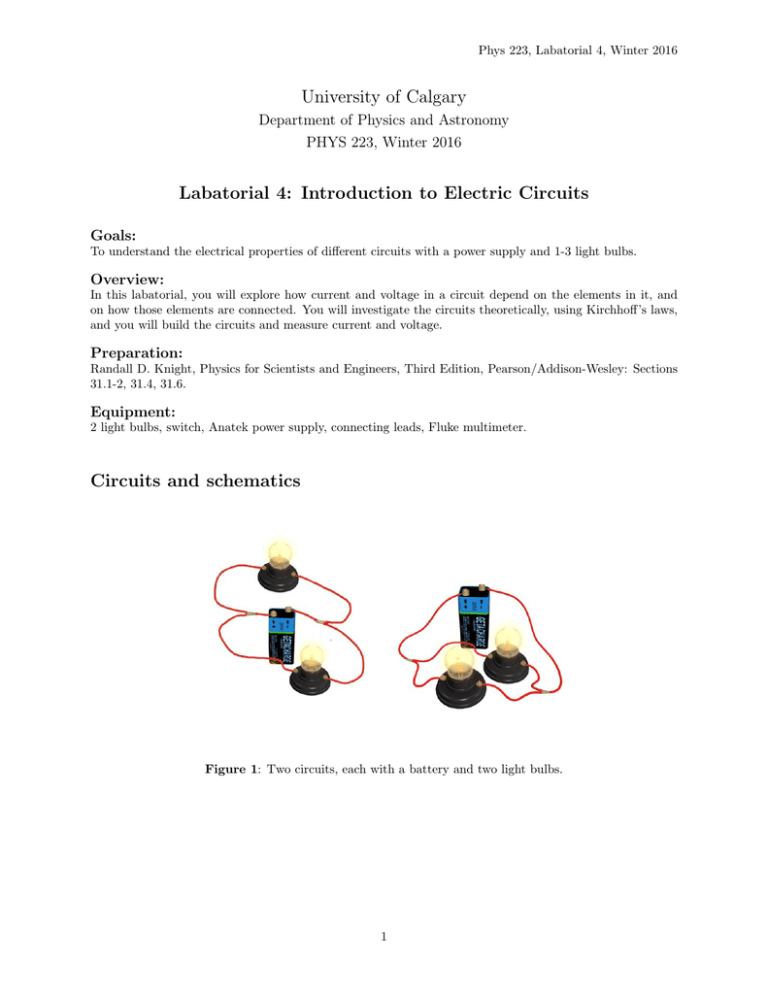
Figure 1: Two circuits, each with a battery and two light bulbs.
1
Phys 223, Labatorial 4, Winter 2016
Question 1: Look at the photos of the two circuits shown
in Fig.1. These photos show three electrical components arpower supply ranged differently. Draw the circuit diagrams correspond(battery)
ing to these two photos, using the symbols to the left.
light bulb
Question 2: Do the diagrams you have drawn for the previous question look the same? If not, does this
mean that they behave differently? Explain why.
A simple circuit: Power supply and light bulb
Figure 2: A simple circuit with a battery and a light bulb.
Build this circuit. In this labatorial, we will use a power supply as if it were just a battery, i.e. a device that provides a fixed potential difference (also called voltage). You have to
connect the wires to the plus and the minus output of the power supply just like you would
connect them to the positive and negative terminal of the battery.
2
Phys 223, Labatorial 4, Winter 2016
Question 3: Draw the diagram for the circuit shown in Fig. 2. Indicate the direction of the current, and
the direction of the electron flow. (Careful: The direction of the current is defined as the direction in which
positive charges would flow, because the concept of current was introduced before people knew what the
actual charge carriers were. Electrons are negatively charged. Many high school physics books only mention
the electron current, not the conventional current I that we use in this course.)
Question 4: How do you expect the current in the wire from the positive terminal of the power supply to
the light bulb and the current in the wire from the light bulb to the negative terminal of the power supply
to compare? Explain your answer.
Question 5: Draw the circuit diagram again, and indicate where the multimeter should be put to measure
the current from the positive terminal of the power supply to the light bulb. Explain your choice.
Question 6: Now use the multimeter in the circuit to check your answer to question 5: Turn off the power
supply. Remove the wire from the positive terminal of the power supply to the light bulb, and replace it
with the multimeter. Then connect the multimeter with the power supply and with the light bulb. Make
sure that the settings on the multimeter are correct for measuring current.
3
Phys 223, Labatorial 4, Winter 2016
CHECKPOINT 1: Before moving on to the next part, have your TA check
the results you obtained so far.
Question 7: Switch the power supply back on and measure the current. Repeat the procedure on the other
side of the circuit to measure the current there, and record the results.
Question 8: What do you expect the potential difference between two points along the wire from the
positive terminal of the power supply to the light bulb to be? (Hint: The wire is a conductor. What do you
know about the potential on a conductor?)
Question 9: Before you use the multimeter to check your answer to the previous question: Sketch the circuit
diagram, and indicate where the multimeter should be put to measure the potential difference between two
points along the wire.
Question 10: Now switch off the power supply and include the multimeter in your circuit, following your
diagram. The multimeter should be connected to one terminal of the power supply and the side of the light
bulb to which this terminal is connected. Before you switch the power supply back on, ask your TA
to check your circuit. Measure the voltage between two points along the wire.
4
Phys 223, Labatorial 4, Winter 2016
Many of the following questions will ask you to think about a situation first, and then check
your prediction with a measurement (just like you did in the previous questions). Wherever
you see a question with “Hypothesis” and “Result” written below, first state your hypothesis
including an explanation for it, and then explore the situation experimentally. Your TA will
mark how well you explain your hypothesis, not whether it is correct.
Question 11: What is the potential difference across the light bulb?
Hypothesis:
Result:
V
Question 12: Draw a graph that
shows the potential along the circuit,
for the parts of the circuit between
points A and B.
A
B
A
B
Question 13: Write down Kirchhoff’s loop law for the circuit. What follows for the relation between the
potential difference ∆Vbulb across the light bulb and the potential difference ∆Vps between the terminals of
the power supply?
5
Phys 223, Labatorial 4, Winter 2016
Question 14: Which conservation law corresponds to Kirchhoff’s loop law? Explain your answer.
I
Question 15: Draw a graph that shows the current
along the circuit, for the parts of the circuit between
points A and B.
A
B
A
B
CHECKPOINT 2: Before moving on to the next part, have your TA check
the results you obtained so far.
A circuit with a power supply and two identical light bulbs
A
Question 16: Are these light bulbs in series or parallel? Explain your answer by writing down the definition of “in series” or “in parallel”.
B
D
C
6
Phys 223, Labatorial 4, Winter 2016
Question 17: Rank the magnitudes of the current at points A, B, C and D.
Hypothesis:
Result:
Question 18: Rank the magnitudes of the potential differences ∆VAB between points A and B, ∆VBC ,
∆VCD , and ∆VDA .
Hypothesis:
Result:
V
Question 19: Draw a graph that shows the potential along the circuit (for the parts of the circuit
between points D and C).
D
A
B
C
Question 20: Write down Kirchhoff’s loop law for the circuit and explain how it is reflected in your graph
for question 22.
7
Phys 223, Labatorial 4, Winter 2016
Question 21: If the light bulb between points B and C is unscrewed from its socket, what will happen to
the current? What will happen to the potential difference between points B and C?
Hypothesis:
Result:
Another circuit with a power supply and two identical light bulbs
A
C
E
B
D
F
Question 22: Are these light bulbs in series or parallel? Explain your answer by writing down the definition of “in series” or “in parallel”.
Question 23: Write down Kirchhoff’s loop law for this circuit. Then, use it to explain why the two circuits
in Fig.1 are electrically equivalent.
Question 24: Build the circuit. Rank the magnitudes of the current at points A-F. (Remember that the
light bulbs are identical.)
Hypothesis:
Result:
8
Phys 223, Labatorial 4, Winter 2016
Question 25: Rank the magnitudes of the potential differences ∆VCD between points C and D, ∆VEF ,
∆VAC , ∆VAE , ∆VAF , and ∆Vps across the power supply.
Hypothesis:
Result:
Question 26: What will happen to the current at point A, if the light bulb between E and F is unscrewed
from its socket?
Hypothesis:
Result:
Question 27: What will happen to the current through the light bulb between C and D, if the light bulb
between E and F is unscrewed from its socket?
Hypothesis:
Result:
Question 28: What will happen to the voltage between points C and D, and between points E and F, if
the light bulb between E and F is unscrewed from its socket?
Hypothesis:
Result:
Last Checkpoint! Clean up your area, and put the equipment back the way
you found it. Call your TA over to check your final work.
9


