Laboratory 3 Thevenin`s Theorem
advertisement

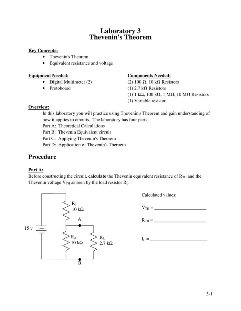
Laboratory 3 Thevenin's Theorem Key Concepts: • Thevenin's Theorem • Equivalent resistance and voltage Equipment Needed: • Digital Multimeter (2) • Protoboard Components Needed: (2) 100 Ω, 10 kΩ Resistors (1) 2.7 kΩ Resistors (1) 1 kΩ, 100 kΩ, 1 MΩ, 10 MΩ Resistors (1) Variable resistor Overview: In this laboratory you will practice using Thevenin's Theorem and gain understanding of how it applies to circuits. The laboratory has four parts: Part A: Theoretical Calculations Part B: Thevenin Equivalent circuit Part C: Applying Thevenin's Theorem Part D: Application of Thevenin's Theroem Procedure Part A: Before constructing the circuit, calculate the Thevenin equivalent resistance of RTH and the Thevenin voltage VTH as seen by the load resistor RL. Calculated values: R1 10 kΩ VTH = ______________________ A RTH = ______________________ 15 v R2 10 kΩ RL 2.7 kΩ IL = ________________________ B 3-1 Now measure the voltage across the load resistor and the current through it. Measured Values: VRL = _____________________ IRL = _____________________ Question: How do the currents compare? How does the measured voltage compare to the Thevenin equivalent voltage? Why should this be? Part B Construct the Thevenin equivalent circuit using the voltage and resistance calculated above. Measure the voltage across the load resistor and the current through it. Measured Values RTH A VL = ________________________ RL 2.7 kΩ VTH IL = _________________________ B Question: How do the measured current and voltage compare to the calculated Thevenin values and to the values measured above? 3-2 Part C Construct the circuit below, using a 1 kΩ resistor as RL. Measure the current IL through RL. Record the resistance and current values in the table, and repeat the measurements with values of 10 kΩ, 100 kΩ, 1 MΩ for RL. R 10 MΩ Resistance RL (Ω) Current IL (A) A 5v RL B Question: What can we say about IL as long as RL« R? In other words, the 5 v power supply and R act like a constant ________ source? Why is this? Question: As far as RL is concerned, is there any difference between your original circuit in Part A and your Thevenin equivalent circuit in Part B? Explain. Question: In terms of VTH and RTH in Part B, what is the open-circuit voltage (Voc) between A and B? (That is, the voltage between A and B as RL → ∞.) Question: In terms of VTH and RTH in Part B, what is the short-circuit current (Isc)? (That is, the current at A as RL → 0.) Question: How is RTH related to Voc and Isc? 3-3 Part D: Construct the circuit below. R2 should be a variable resistor, and R4 is the unknown. R1 R3 B A R2 R4 Question: Use the results of Thevenin's Theorem applied to this circuit to show how R4 may be determined. Determine the value of R4 using your results from above: R4 = ________________________ Use the DMM to measure the value of R4 directly: R4 = ________________________ Question: How do the two values compare? Which do you think is a better estimate? Why? 3-4


