Multiple junction biasing of superconducting tunnel junction detectors
advertisement
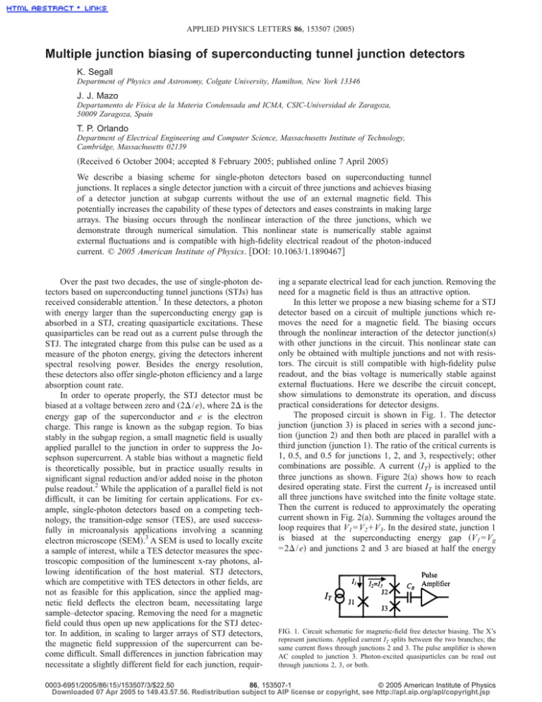
APPLIED PHYSICS LETTERS 86, 153507 共2005兲 Multiple junction biasing of superconducting tunnel junction detectors K. Segall Department of Physics and Astronomy, Colgate University, Hamilton, New York 13346 J. J. Mazo Departamento de Física de la Materia Condensada and ICMA, CSIC-Universidad de Zaragoza, 50009 Zaragoza, Spain T. P. Orlando Department of Electrical Engineering and Computer Science, Massachusetts Institute of Technology, Cambridge, Massachusetts 02139 共Received 6 October 2004; accepted 8 February 2005; published online 7 April 2005兲 We describe a biasing scheme for single-photon detectors based on superconducting tunnel junctions. It replaces a single detector junction with a circuit of three junctions and achieves biasing of a detector junction at subgap currents without the use of an external magnetic field. This potentially increases the capability of these types of detectors and eases constraints in making large arrays. The biasing occurs through the nonlinear interaction of the three junctions, which we demonstrate through numerical simulation. This nonlinear state is numerically stable against external fluctuations and is compatible with high-fidelity electrical readout of the photon-induced current. © 2005 American Institute of Physics. 关DOI: 10.1063/1.1890467兴 Over the past two decades, the use of single-photon detectors based on superconducting tunnel junctions 共STJs兲 has received considerable attention.1 In these detectors, a photon with energy larger than the superconducting energy gap is absorbed in a STJ, creating quasiparticle excitations. These quasiparticles can be read out as a current pulse through the STJ. The integrated charge from this pulse can be used as a measure of the photon energy, giving the detectors inherent spectral resolving power. Besides the energy resolution, these detectors also offer single-photon efficiency and a large absorption count rate. In order to operate properly, the STJ detector must be biased at a voltage between zero and 共2⌬ / e兲, where 2⌬ is the energy gap of the superconductor and e is the electron charge. This range is known as the subgap region. To bias stably in the subgap region, a small magnetic field is usually applied parallel to the junction in order to suppress the Josephson supercurrent. A stable bias without a magnetic field is theoretically possible, but in practice usually results in significant signal reduction and/or added noise in the photon pulse readout.2 While the application of a parallel field is not difficult, it can be limiting for certain applications. For example, single-photon detectors based on a competing technology, the transition-edge sensor 共TES兲, are used successfully in microanalysis applications involving a scanning electron microscope 共SEM兲.3 A SEM is used to locally excite a sample of interest, while a TES detector measures the spectroscopic composition of the luminescent x-ray photons, allowing identification of the host material. STJ detectors, which are competitive with TES detectors in other fields, are not as feasible for this application, since the applied magnetic field deflects the electron beam, necessitating large sample–detector spacing. Removing the need for a magnetic field could thus open up new applications for the STJ detector. In addition, in scaling to larger arrays of STJ detectors, the magnetic field suppression of the supercurrent can become difficult. Small differences in junction fabrication may necessitate a slightly different field for each junction, requir- ing a separate electrical lead for each junction. Removing the need for a magnetic field is thus an attractive option. In this letter we propose a new biasing scheme for a STJ detector based on a circuit of multiple junctions which removes the need for a magnetic field. The biasing occurs through the nonlinear interaction of the detector junction共s兲 with other junctions in the circuit. This nonlinear state can only be obtained with multiple junctions and not with resistors. The circuit is still compatible with high-fidelity pulse readout, and the bias voltage is numerically stable against external fluctuations. Here we describe the circuit concept, show simulations to demonstrate its operation, and discuss practical considerations for detector designs. The proposed circuit is shown in Fig. 1. The detector junction 共junction 3兲 is placed in series with a second junction 共junction 2兲 and then both are placed in parallel with a third junction 共junction 1兲. The ratio of the critical currents is 1, 0.5, and 0.5 for junctions 1, 2, and 3, respectively; other combinations are possible. A current 共IT兲 is applied to the three junctions as shown. Figure 2共a兲 shows how to reach desired operating state. First the current IT is increased until all three junctions have switched into the finite voltage state. Then the current is reduced to approximately the operating current shown in Fig. 2共a兲. Summing the voltages around the loop requires that V1 = V2 + V3. In the desired state, junction 1 is biased at the superconducting energy gap 共V1 = Vg = 2⌬ / e兲 and junctions 2 and 3 are biased at half the energy FIG. 1. Circuit schematic for magnetic-field free detector biasing. The X’s represent junctions. Applied current IT splits between the two branches; the same current flows through junctions 2 and 3. The pulse amplifier is shown AC coupled to junction 3. Photon-excited quasiparticles can be read out through junctions 2, 3, or both. 0003-6951/2005/86共15兲/153507/3/$22.50 86, 153507-1 © 2005 American Institute of Physics Downloaded 07 Apr 2005 to 149.43.57.56. Redistribution subject to AIP license or copyright, see http://apl.aip.org/apl/copyright.jsp 153507-2 Appl. Phys. Lett. 86, 153507 共2005兲 Segall, Mazo, and Orlando FIG. 2. 共a兲 Hysteretic dynamics for the circuit shown in Fig. 1. IT is plotted against the voltage for junctions 1 共dotted line兲, 2, and 3 共both solid lines兲. IT is initially increased until the three junctions switch to nonzero voltage; then the current is decreased. At the bias current, junctions 2 and 3 are in the subgap region where they can function as photon detectors; here nearly all the current IT is flowing through junction 1. 共b兲 I-V curves showing the subgap current for junctions 2 and 3. I2 = I3 is plotted versus V3, solid line, and 共Vg − V3兲 dotted line. The two lower curves are for a temperature 共kT/ ⌬ = 1 / 9兲 and the two upper curves are for 共kT/ ⌬ = 1 / 8兲. At the lower temperature, the intersection of the two curves gives the operating point. The heat from a photon coupled to both junctions causes the system to move from A to B, straight up. Heat only coupled to one of the junctions causes it to move to the left. gap 共V2 = V3 = Vg / 2兲. At this point junctions 2 and/or 3 can function as a detector; no magnetic field has been applied.4 We first show nonlinear simulations of the biasing state and then discuss practical considerations for detector design. To simulate the circuit, we solve the usual RSJ model5 for each junction with an added term for the subgap current. The normalized current through junction j is given by ij = hj 冉 冊 d 2 j d j + sin j + iss共 j兲 , 2 + ⌫共 j兲 d d 共1兲 where is the phase difference across a given junction, is its normalized voltage 共 = d / d兲, = pt is the normalized time, p is the plasma frequency, t is time, ⌫共兲 is the voltage-dependent damping, h is the anisotropy parameter for the size of the different junctions, and iss is the voltagedependent subgap current. The subscript j runs over the three junctions in the circuit. The currents i j are normalized to the critical current of the first junction, Ic1. The plasma frequency p is given by 2p = 2Ic ⌽0C , where ⌽0 is the flux quantum and C is the junction capacitance. The theoretical BCS subgap current, iss, depends exponentially on temperature and is given in Ref. 6. The nonlinear damping parameter ⌫ is given by ⌫ = ⌫Ng共兲, where ⌫N is the damping in the normal state, given by ⌫N2 = ⌽0 2ICRN2 C , and g共兲 is the voltage-dependent damping. To account for the damping in the subgap region and for the gap rise, we use the following empirical form for g共兲:7 Ⲑ Ⲑ g共兲 = gsg + 再 冋 冉 冊册冎 1 − gsg j 1 − tanh 100 1 − 2 g , 共2兲 where gsg is a constant damping in the subgap region and g is the normalized gap voltage. Equation 共2兲 gives ⌫共兲 = gsg⌫N for V ⬍ 共2⌬ / e兲 and ⌫共兲 = ⌫N for V ⬎ 共2⌬ / e兲. To write the equations of the circuit we use fluxoid quantization and current conservation. Fluxoid quantization gives 共1 − 2 − 3兲 = 2 f ind, where f ind is the induced frustration in the loop formed by the three junctions. Current conservation gives i1 = i / 2 − im and i2 = i3 = i / 2 + im; here i j is given by Eq. 共1兲, i = i1 + i2, and im, the mesh current, is related with f ind through im = 2f ind. The parameter = ⌽0 / 共2LIc1兲 measures the importance of induced fields; L is the geometric inductance of the loop.8 The results of the model are shown in Fig. 2共a兲. The parameters used are ⌫N = 0.02, h1 = 1, h2 = 0.5, h3 = 0.5, gsg = 10−4, and = 10. Initially, as IT is increased, all three junctions are in the zero-voltage state. At a current of approximately IT = 1.3Ic1 the system switches to a running mode, where V1 = Vg and V2 = V3 = 共Vg / 2兲. In real experiments the switching of the three junctions is affected by fluctuations, which are not included in Fig. 2共a兲. In any case, for reaching a detector biasing point, these switching dynamics are unimportant; one simply increases the current to a value large enough to ensure that all three junctions have switched. Once this point has been reached, the current is then decreased to the operating current shown, approximately IT = 0.2Ic1. Operating currents as large as IT = 0.5Ic1 give stable dynamics, but for noise purposes lower values of IT are more desirable. Following this procedure ensures the desired state will be obtained. If the current is decreased further, the system will retrap to the zero voltage state across all three junctions. Figure 2共a兲 plots the total current IT on the y axis; at the operating point shown, nearly all of this current IT is flowing though junction 1. Only the small subgap current flows through junctions 2 and 3. This subgap current for two different temperatures is shown by the solid lines in Fig. 2共b兲; they resemble a typical STJ I–V curve. This state of the detector was motivated by a type of nonlinear dynamical state in a Josephson array called a breather, which is an intrinsically localized mode that exists in a ladder array driven by a uniform current.9 The so-called type B breather has a similar voltage pattern of Vg, Vg / 2, and Vg / 2 for three junctions around a loop. Although not identical, the circuit in Fig. 1 has similar hysteretic dynamics to the type B breather state. We have found that other nonlinear states coexist in the circuit with the desired state. We studied the stability of the detector state against external fluctuations by adding a noise term to each junction in Eq. 共1兲, and find stability for times orders of magnitude longer than typical experimental times. The main fabrication requirement for reaching this biasing state is that the junctions be highly underdamped. Values of ⌫N ⬍ 0.05 result in the ideal dynamics that are shown in Fig. 2共a兲 and 2共b兲. For 0.1⬎ ⌫N ⬎ 0.05, the nonlinear biasing state still exists, but with an increased dc current through junctions 2 and 3, which will result in some excess noise. For ⌫N ⬎ 0.1, the dynamics becomes more complicated than we have shown in Fig. 2共a兲 and 2共b兲. For niobium 共Nb兲 junctions, achieving ⌫N ⬍ 0.05 requires fabricating a current density 共Jc兲 of about 200 A / cm2 or less, which is satisfied by most detector junctions tested to date. For aluminum 共Al兲 junctions the current density should be lower, around Jc ⬃ 5 A / cm2. This is achievable in most fabrication processes, although many Al junctions tested to date have values of Jc slightly higher, around 30 A / cm2. The loop inductance parameter, , appears to have no major constraints.10 We comment more on the possible circuit parameters in a future paper.11 With the circuit biased at the desired operating point, away from the hysteresis and switching in Fig. 2共a兲, a simpler dc model can be used to predict currents and voltages at Downloaded 07 Apr 2005 to 149.43.57.56. Redistribution subject to AIP license or copyright, see http://apl.aip.org/apl/copyright.jsp 153507-3 Appl. Phys. Lett. 86, 153507 共2005兲 Segall, Mazo, and Orlando the operating point of the circuit with the same accuracy as the full model. These results can be used to show the operation of the detector in response to an absorbed photon and to discuss issues of impedance and noise. In the dc model, we change Eq. 共1兲 to i j = h jb⌫共v j兲v j + iss共v j兲c and keep the relations V1 = V2 + V3; i2共V2兲 = i3共V3兲; and i = i1共V1兲 + i2共V2兲, defining a system of algebraic equations which can be numerically solved. At the operating point V1 = Vg and V2 = 共Vg − V3兲. We can then solve the dc model equations graphically by plotting I3 = I2 vs V2 and versus 共Vg − V3兲 The intersection gives the operating point of the circuit, as shown in Fig. 2共b兲. To simulate the response to a photon, we increase the temperature of the detector junction. In a real detector the temperature first increases, as the excess quasiparticles tunnel through the junction, and then decreases, as the quasiparticles either recombine or diffuse away from the barrier. The detector junction共s兲 can be junction 2, junction 3, or both. The temperature of junction 1 stays constant. In Fig. 2共b兲 we show how the operating point can be followed as the subgap current increases. In the case of heating both junctions 2 and 3, the operating point moves straight up from A to B, and then back down from B to A. If only junction 3 is used then it moves to the left and up. To read out the excess tunneling current, a current amplifier can be AC coupled in parallel with junction 3, as shown in Fig. 1; the capacitor 共CB兲 passes signal frequencies and blocks DC currents. The extra junctions in the circuit will add additional electronic noise to the amplifier which can potentially degrade the energy resolution of the detector. In many cases the additional noise will cause only a small, even negligible change in the total energy resolution. Under some conditions, the cost can be as large as a factor of two in the energy width. The two main sources of electronic noise are 共i兲 the shot noise due to the current flowing through the junctions, and 共ii兲 the voltage noise of the amplifier, which is converted to current noise due to the junction impedance.12 The shot noise 共i兲 is proportional to the dc current flowing through each junction. The current flowing through junctions 2 and 3 is the same subgap current that usually flows through a single junction; hence there is no increase over the usual shot noise. The extra current flowing in junction 1 will give some additional shot noise; however, since the impedance of junction 1, biased at the energy gap, is many orders of magnitude smaller than the impedance of junctions 2 and 3, this extra noise current will almost exclusively flow through junction 1 and not through junctions 2 and 3. Thus, it will not add significantly to the total shot noise seen by the amplifier. For the voltage noise 共ii兲, the new impedance seen by the amplifier will be approximately junction 2 in parallel with junction 3. If junctions 2 and 3 have the same dynamic resistance, then the new impedance seen by the amplifier will be a factor of two smaller than the impedance of junction 2 or 3 individually. This increases the contribution of the amplifier voltage noise to the total current noise by a factor of two as compared to a single junction. The actual amount of increase in the energy width caused by the increases in electronic noise will depend on the particular detector geometry, photon energy, and junction size. In addition, the bias current IT can be tuned for optimal noise performance just as the bias current and magnetic field are tuned in existing STJ detectors. In addition to noise there are other possible considerations for detector design. In our models we have assumed the theoretical BCS subgap current 共iss兲 along with an additional linear subgap impedance 共gsg兲. In real devices there are often other contributions to the subgap current, including Fiske modes, normal metal tunneling, and multiparticle Andreev reflection. The importance of these issues will need to be determined through experiments and junction fabrication. A few points should be noted, however. The first is that one need not be constrained by the ratio of 1.0, 0.5, and 0.5 for the critical currents of the three junctions. We have seen that several different ratios give subgap biasing, such as 1.0, 0.5, and 0.3. Different ratios will result in different operating voltages in the subgap region, which can be chosen to avoid any known subgap features. In addition, by using the technique we have described, junction shapes will not be as constrained as they are presently. In existing devices, junction shapes are usually “stretched” in order to allow more efficient supercurrent suppression by the external magnetic field. Since the external field is no longer needed, the junctions can be chosen to be any shape. This would help, for example, in avoiding Fiske modes.13 Finally, since two of the junctions in the circuit can each be used as a detector, there are possibilities to bias a two-junction detector or even a many-pixel array in the future with this technique. This will free up electrical leads and offer more design flexibility. We thank E. Trìas, D. E. Prober, M. C. Gaidis, S. Friedrich, and L. Frunzio for useful discussions. We acknowledge the FEDER program 共BMF2002-00113兲, NSF 共DMR-9988832兲, and the Colgate Division of Natural Sciences. J. Mather, Nature 共London兲 401, 654 共1999兲; N. E. Booth and D. J. Goldie, Supercond. Sci. Technol. 9, 493 共1996兲. 2 It is possible to bias a single junction without a magnetic field using a small resistor, but this will then draw the photon-induced current away from the amplifier. Alternately, an active voltage bias can be provided by the signal amplifier; however, real experiments show that, in this case, a magnetic field is still necessary. 3 D. A. Wollman, S. W. Nam, G. C. Hilton, K. D. Irwin, N. F. Bergren, D. A. Rudman, J. M. Martinis, and D. E. Newbury, J. Microsc. 199, 37 共2000兲. 4 Aluminum tunnel junctions, which are often used for detectors, typically have an increase in DC current at this value of voltage, Vg / 2. As we state later in the paper, it is straightforward to change the ratio of the three critical currents slightly, which avoids biasing the detector at exactly this subgap feature. 5 T. P. Orlando and K. A. Delin, Foundations of Applied Superconductivity 共Addison-Wesley, Reading, MA, 1991兲. 6 T. Van-Duzer and C. W. Turner, Principles of Superconductive Devices and Circuits 共Edward Arnold, London, UK, 1981兲. 7 This constant subgap damping adds a linear current to the subgap current in Eq. 共1兲. We chose a value for this subgap damping which adds less about 10% to the BCS subgap value. This was chosen empirically, to try to match a typical experimental I–V curve. 8 When deriving the equations we have neglected external magnetic fields and have assumed that the left and right branches of the circuit have the same geometrical inductance; the model can be easily adapted to account for these effects. 9 E. Trias, J. J. Mazo, and T. P. Orlando, Phys. Rev. Lett. 84, 741 共2000兲; P. Binder, D. Abraimov, A. V. Ustinov, S. Flach, and Y. Zolotaryuk, Phys. Rev. Lett. 84, 745 共2000兲. 10 Using ⫽0.1, ⫽1, or running the simulation in the limit of no induced fields all give similar results. 11 K. Segall, J. J. Mazo, and T. P. Orlando, IEEE Trans. Appl. Supercond. 共to be published兲. 12 K. Segall, C. Wilson, L. Frunzio, L.Li, S.Friedrich, M.C.Gaidis, D.E.Prober, and A.E.Szymkowiak, Appl. Phys. Lett. 76, 3998 共2000兲. 13 M. D. Fiske, Rev. Mod. Phys. 36, 221 共1964兲. Downloaded 07 Apr 2005 to 149.43.57.56. Redistribution subject to AIP license or copyright, see http://apl.aip.org/apl/copyright.jsp 1


