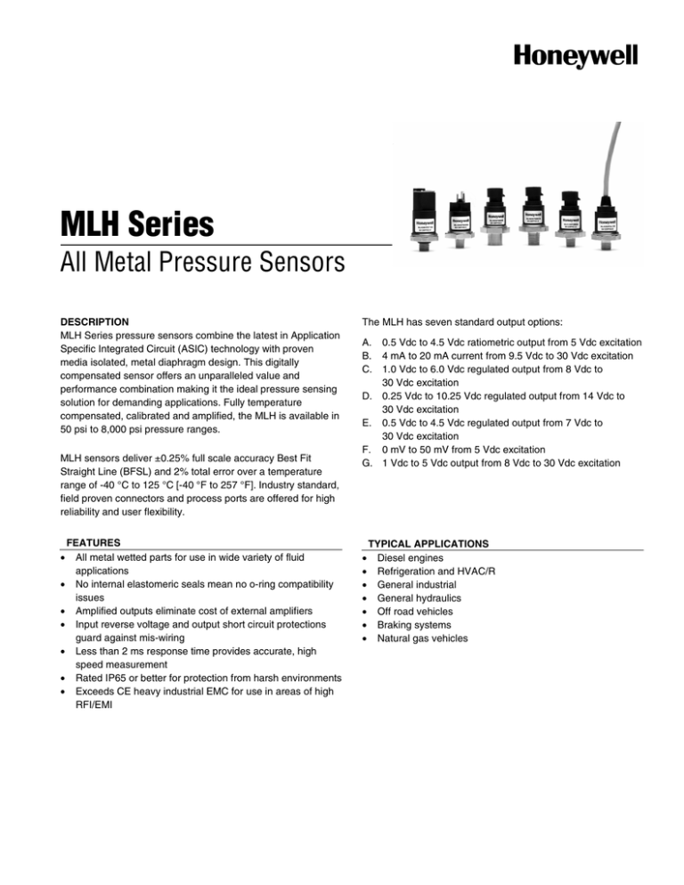
MLH Series
All Metal Pressure Sensors
DESCRIPTION
MLH Series pressure sensors combine the latest in Application
Specific Integrated Circuit (ASIC) technology with proven
media isolated, metal diaphragm design. This digitally
compensated sensor offers an unparalleled value and
performance combination making it the ideal pressure sensing
solution for demanding applications. Fully temperature
compensated, calibrated and amplified, the MLH is available in
50 psi to 8,000 psi pressure ranges.
MLH sensors deliver ±0.25% full scale accuracy Best Fit
Straight Line (BFSL) and 2% total error over a temperature
range of -40 °C to 125 °C [-40 °F to 257 °F]. Industry standard,
field proven connectors and process ports are offered for high
reliability and user flexibility.
FEATURES
All metal wetted parts for use in wide variety of fluid
applications
• No internal elastomeric seals mean no o-ring compatibility
issues
• Amplified outputs eliminate cost of external amplifiers
• Input reverse voltage and output short circuit protections
guard against mis-wiring
• Less than 2 ms response time provides accurate, high
speed measurement
• Rated IP65 or better for protection from harsh environments
• Exceeds CE heavy industrial EMC for use in areas of high
RFI/EMI
•
The MLH has seven standard output options:
A.
B.
C.
0.5 Vdc to 4.5 Vdc ratiometric output from 5 Vdc excitation
4 mA to 20 mA current from 9.5 Vdc to 30 Vdc excitation
1.0 Vdc to 6.0 Vdc regulated output from 8 Vdc to
30 Vdc excitation
D. 0.25 Vdc to 10.25 Vdc regulated output from 14 Vdc to
30 Vdc excitation
E. 0.5 Vdc to 4.5 Vdc regulated output from 7 Vdc to
30 Vdc excitation
F. 0 mV to 50 mV from 5 Vdc excitation
G. 1 Vdc to 5 Vdc output from 8 Vdc to 30 Vdc excitation
•
•
•
•
•
•
•
TYPICAL APPLICATIONS
Diesel engines
Refrigeration and HVAC/R
General industrial
General hydraulics
Off road vehicles
Braking systems
Natural gas vehicles
MLH Series
SPECIFICATIONS (All specifications are measured at 25 °C [77 °F] and at rated excitation unless otherwise specified.)
Pressure Ranges (Comparable metric units follow same proof and burst specifications)
Units (psi)
psiG
psiG
psiG
psiG
psiG
psiS
psiS
psiS
Pressure
50
100
150
200
250
300
500
1000
Proof pressure
150
300
450
600
750
900
1500
2000
Burst pressure
500
1000
1500
2000
2500
3000
5000
10000
psiS
2000
4000
20000
psiS
3000
6000
30000
psiS
5000
7500
30000
psiS
8000
12000
30000
Units (bar)
barG
barG
barG
barS
barS
barS
barS
barS
barS
barS
barS
barS
Pressure
6
10
16
25
40
60
100
160
250
350
500
550
Proof pressure
18
30
48
75
80
120
200
320
500
700
750
825
Burst pressure
60
100
160
250
400
600
1000
1600
2068
2068
2068
2068
Physical
Material in contact with
Stainless steel and Haynes 214 alloy (or equivalent) (all wetted materials are equivalent or better than 300
media
series stainless steel). High corrosion resistant Hastelloy C22 sensor available (contact factory).
Housing material
Black plastic – Amodel AS-4133 HS – PPA
Weight
57.0 g [2.0 oz]
Environmental
Shock
50 g peak [5 ms], 100 g peak [11 ms]
Vibration
Figure 514.2-5, Curve AK, Table 514.2-V, Random Vibration Test [overall g rms = 20.7 min.]
Electrical
Ratiometric
Current
Regulated
Regulated
Regulated
milliVolt
Regulated
(B)
©
(D)
(E)
(F)
(G)
(A)
Zero output
0.5 Vdc
4.0 mA
1.0 Vdc
0.25 Vdc
0.5 Vdc
0 ±2.5 mV
1.0 Vdc
Full scale
4.0 Vdc
16 mA
5.0 Vdc
10.0 Vdc
4.0 Vdc
50 mV
4.0 Vdc
1
output
(0.5 to 4.5 Vdc)
(4 to 20 mA)
(1.0 to 6.0 Vdc)
(0.25 to 10.25 Vdc) (0.5 to4.5 Vdc)
(0 to 50 mV)
(1.0 to 5.0 Vdc)
Excitation
Supply
current
Source
(nominal)
Sink
(nominal)
5 Vdc ±250 mV
(6.0 Vdc max.)
4.0 mA typical
(8 mA max.)
9.5 Vdc to
30.0 Vdc
1.0 mA
8.0 Vdc to
30.0 Vdc
5.0 mA typical
(17 mA max.)
14.0 Vdc to
30.0 Vdc
5.0 mA typical
(17 mA max.)
7.0 Vdc to
30.0 Vdc
5.0 mA typical
(17 mA max.)
5.0 Vdc
(6.0 Vdc max.)
8.0 mA typical
(17 mA max.)
8.0 Vdc to
30.0 Vdc
5.0 mA typical
(17 mA max.)
N/A
1.0 mA
1.0 mA
1.0 mA
N/A
1.0 mA
1.0 mA
@ zero output
N/A
1.0 mA
@ zero output
1.0 mA
@ zero output
1.0 mA
@ zero output
N/A
1.0 mA
@ zero output
90 db
90 db
90 db
90 db
90 db
N/A
90 db
25 Ω max.
N/A
25 Ω max.
25 Ω max.
25 Ω max.
≥2000 Ω
25 Ω max.
Supply
rejection
ratio
Output
impedance
N/A
Notes: 1. All specifications are measured at 25 ºC [77 ºF] and at rated excitation unless otherwise specified.
Performance
Response time
EMI/RFI
Accuracy
Total error band
Compensated, operating and
storage temperature range
2
<2 ms
• EC Directive 2004/108/EC (consolidated 89/336) Standard IEC 61326 2002
• IEC 61000-4-3-2002 & IEC 61000-4-6
ISO 11452-2
400 MHz to 2 GHz, 100 V/M incl. 1 kHz AM 80%
ISO 11452-4
1MHz to 100MHz, 100 mA incl. 1 kHz AM 80%
±0.25 % F.S.O. best fit straight line. Includes: non-linearity, hysteresis, non-repeatability. Thermal
errors not included. 0.5 % <100 psi.
±2 % FSO includes zero offset error, span error, thermal effect on zero, thermal effect on span, nonlinearity, hysteresis and non-repeatability. (±3 % FSO on ranges <250 psig.)
-40 °C to 125 °C [-40 °F to 257 °F]
www.honeywell.com/sensing
All Metal Pressure Sensors
ORDER GUIDE
MLH 500
P
S
B 06
B
Model
Output
Pressure
Range
PSI
050 500
100 01K
150 02K
200 03K
250 05K
300 08K
BAR
006 100
010 160
016 250
025 350
040 500
060 550
Unit
P = psi
B = bar
K = Kg/cm2
M = MPa
Reference
S = Sealed Gage (psiS)
A = Absolute (psiA)
G = Gage (psiG)
Electrical
Termination
B = Packard MetriPak 150 (IP65)
C = Hirschman (mates with G4W1F) (IP65)
D = M12 x 1 (Brad Harrison micro) (IP67)
F = DIN 72585 (Cannon APD type) (IP69K)
G = DIN43650-C (IP65)
H = Amp Superseal 1.5 (IP67)
L = Cable (1 meter) (IP69K)
M = Cable (3 meter) (IP69K)
P = Flying Leads (20 AWG – 6 in) (IP65)
T
R == Deutsch
DeutschDTM04-3P
DT06-W3S(integral)
(on 15 in(IP67)
cable) (IP69K)
S = Deutsch DT06-W4S (on 15 in cable) (IP69K)
T = Deutsch DTM04-3P (integral) (IP67)
A = 0.5 Vdc to 4.5 Vdc Ratiometric
B = 4 mA to 20 mA Current Loop
C = 1 Vdc to 6 Vdc Regulated
D = 0.25 Vdc to 10.25 Vdc Regulated
E = 0.5 Vdc to 4.5 Vdc Regulated
F = 0 mV to 50 mV
G = 1 Vdc to 5 Vdc Regulated
01 = 1/4-18 NPT
02 = M12 x 1.5
03 = M14 x 1.5
04 = 3/8-24 UNF
05 = M18 x 1.5
06 = 1/8 in-27 NPT
07 = 1/2 in-20 UNF
08 = M10 x 1
09 = 1/4 in SAE female Schrader
10 = 7/16-20 UNF
11 = 1/2 in NPT
12 = 9/16-18 UNF
13 = PT 1/4-19 BSP Tapered Thread
14 = G 1/4-19 per DIN 3852-2
15 = G 1/8 with O Ring Groove
16 = M16 x 1.5
17 = G 1/4 with O Ring Groove
18 = G 1/8 per DIN 3852-2
19 = PT1/8-28 BSP Tapered Thread
20 = M20 x 1.5
Pressure
Connection
Note: Not all combinations are available. Minimum quantity orders apply. Additional pressure ranges and special calibration
versions are available. Contact your local sales representative for assistance.
Honeywell Sensing and Control
3
MOUNTING DIMENSIONS (For reference only. mm/(in).)
PIN AND WIRE CODES
(Option B – Packard)
Pin
Voltage
Current
a
+ Excitation
+ Excitation
b
Output
- Excitation
c
Common
No Connection
A variety of pressure ports and electrical
termination connection options are available.
Refer to the “How to Order” on previous page for
possible combinations. Contact your Honeywell
representative for details.
WARNING
WARNING
MISUSE OF DOCUMENTATION
PERSONAL INJURY
•
DO NOT USE these products as safety or emergency stop
devices or in any other application where failure of the
product could result in personal injury.
Failure to comply with these instructions could result in
death or serious injury.
The information presented in this product sheet is for
reference only. Do not use this document as a product
installation guide.
• Complete installation, operation, and maintenance
information is provided in the instructions supplied with
each product.
Failure to comply with these instructions could result in
death or serious injury.
SALES AND SERVICE
WARRANTY/REMEDY
Honeywell warrants goods of its manufacture as being
free of defective materials and faulty workmanship.
Honeywell’s standard product warranty applies unless
agreed to otherwise by Honeywell in writing; please refer
to your order acknowledgement or consult your local
sales office for specific warranty details. If warranted
goods are returned to Honeywell during the period of
coverage, Honeywell will repair or replace, at its option,
without charge those items it finds defective. The
foregoing is buyer’s sole remedy and is in lieu of all
other warranties, expressed or implied, including
those of merchantability and fitness for a particular
purpose. In no event shall Honeywell be liable for
consequential, special, or indirect damages.
While we provide application assistance personally,
through our literature and the Honeywell web site, it is up
to the customer to determine the suitability of the product
in the application.
Honeywell serves its customers through a worldwide
network of sales offices, representatives and distributors.
For application assistance, current specifications, pricing
or name of the nearest Authorized Distributor, contact
your local sales office or:
E-mail: info.sc@honeywell.com
Internet: www.honeywell.com/sensing
Phone and Fax:
Asia Pacific
+65 6355-2828
+65 6445-3033 Fax
Europe
+44 (0) 1698 481481
+44 (0) 1698 481676 Fax
Latin America +1-305-805-8188
+1-305-883-8257 Fax
USA/Canada +1-800-537-6945
+1-815-235-6847
+1-815-235-6545 Fax
Specifications may change without notice. The
information we supply is believed to be accurate and
reliable as of this printing. However, we assume no
responsibility for its use.
Automation and Control Solutions
Sensing and Control
Honeywell
1985 Douglas Drive North
Minneapolis, MN 55422
www.honeywell.com/sensing
008118-4-EN IL50 GLO Printed in USA
October 2006
Copyright © 2006. Honeywell International Inc. All rights reserved.

