FS1000 Series
Fast Switching Synthesizer
Supports hundreds of fast switching, high spectral purity applications.
Description:
Features:
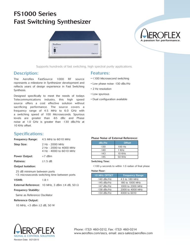
The Aeroflex FastSource 1000 RF source
represents a milestone in Synthesizer development and
reflects years of design experience in Fast Switching
Synthesis.
• <100 Microsecond switching
Designed specifically to meet the needs of todays
Telecommunications industry, this high speed
source offers a cost effective solution without
sacrificing performance. The source covers a
frequency range of 4.5 MHz to 6.0 GHz with
a switching speed of 100 Microseconds. Spurious
levels are greater than -65 dBc and Phase
noise at 1.0 GHz is greater than -130 dBc/Hz at
10 KHz offset.
• Low phase noise -130 dBc/Hz
• 2 Hz resolution
• Low spurious
• Dual configuration available
Specifications:
Phase Noise of External Reference:
Frequency Range:
4.5 MHz to 6010 MHz
Step Size:
2 Hz - 2000 MHz
2 Hz - 2000 to 4000 MHz
4 Hz - 4000 to 6010 MHz
Power Output:
+7 dBm
Flatness:
±1.5 dB
-130
-140
-143
-145
Offset
100 Hz
1 KHz
10 KHz
50 KHz
Switching Time:
<100 µ seconds to within 1.0 radian of final phase
Output Isolation:
25 dB minimum between ports
<5 microseconds switching time between ports
VSWR:
dBc/Hz
1.8:1
External Reference: 10 MHz, 3 dBm ±4 dB, 50 W
Frequency Stability:
Same as Reference Oscillator
Noise Floor:
10 MHz OFFSET
-140 dBc/Hz
-145 dBz/Hz
-147 dBc/Hz
-138 dBc/Hz
-134 dBc/Hz
Frequency Range
4.5 to 180 MHz
180 to 1000 MHz
1000 to 2000 MHz
2000 to 4000 MHz
4000 to 6010
Reference Output:
10 MHz, +3 dBm ±2 dB, 50 W
SIGNAL & CONTROL SOLUTIONS
Revision Date: 8/21/2013
Phone: (732) 460-0212, Fax: (732) 460-0214
www.aeroflex.com/ascs, email: ascs-sales@aeroflex.com
FS1000 Series
Fast Switching Synthesizer
SIGNAL & CONTROL SOLUTIONS
Specifications (con’t):
Residual FM:
Output Phase Noise:
OFFSET
<250 MHz
.25 to
<.5 GHz
0.5 to
<1.0 GHz
1.0 to
<2.0 GHz
2.0 to
<4.0 GHz
4.0 to
<6.0 GHz
Typ.
Guar.
Typ.
Guar.
Typ.
Guar.
Typ.
Guar.
Typ.
Guar.
Typ.
Guar.
10 kHz
-125
-122
-135
-132
-131
-127
-125
-122
-119
-116
-113
-110
20 kHz
-127
-124
-137
-133
-133
-129
-127
-124
-121
-118
-115
-112
100
kHz
-128
-125
-138
-134
-134
-130
-128
-123
-122
-118
-116
-113
Residual FM
<7
<16
< 32
Frequency Range
4 to 2000 MHz
2000 to 4000 MHz
4000 to 6010MHz
Frequency Control:
Parallel BCD positive or negative true with strobe. Strobe normally
low, trigger on trailing edge
Output Fault:
Remote On/Off (RF): O MHz = Off
On/Off Ratio
<25 dBc
Harmonics
-25 dBc max.
TTL level logic, “1” normal operation
4.5 to 6010 MHz
Sub Harmonics:
Logic Connector:
50 Pin receptacle, AMP 554216-3
-60 dBc, Typical
-50 dBc Max except for components at FC noted below
Initialization:
Unit will initialize with RF Off
@ FC=4.0 to 4.25, 5F/2 may be -45 dBc
@ Offsets ≤±2.8 MHz from the carrier, spurs will be as follows:
Random Vibration:
10 Hz to 300 Hz @ 1.2 G RMS
Power:
105 to 125 VAC, 50-60 Hz
FC <180 MHz: 180 MHz<FC<1.0 GHz
1.0 GHz<FC<2.0 GHz
2.0 GHz<FC<4.0 GHz
4.0 GHz<FC<6.01 GHz
-60
-66
-60
-54
-48
Temperature Range: +10o to +45 oC
dBc
dBc
dBc
dBc
dBc
CONFIGURATION
S = Single Synthesizer
D = Dual, Two independent synthesizers in a common chassis
For 1.0 GHz<FC <2 GHz, fixed spurs at the following frequencies may
be -60 dBc: 1175, 1225, 1275, 1325, 1375, 1425, 1475, 1525,
1575 and 1625 MHz
Spurious:
dBc (maximum)
-65
-60
-55
Frequency Range
4 to 2000 MHz
2000 to 4000 MHz
4000 to 6010MHz
For FC less than 180 MHz a spur may exist between 1609 Mz and
1960 MHz at -35 dBc: A fixed 800 MHz spur may exist at -60 dBc
all carrier frequencies
Physical Dimensions:
Dimensions:
16.75” W X 5.22” H X 23.86” D
2
Aeroflex Signal & Control Solutions
www.aeroflex.com/ASCS • acc-sales@aeroflex.com
Revision Date: 8/21/2013
FS1000 Series
Fast Switching Synthesizer
SIGNAL & CONTROL SOLUTIONS
Programming Input (BCD Connector)
SIGNAL
PIN
SIGNAL
PIN
Logic Ground
50
NC
25
400 MHz
49
Strobe
24
NC
48
NC
23
NC
47
NC
22
NC
46
Chassis
Ground
21
Fault
45
8 MHz
20
200 MHz
44
4 MHz
19
100 MHz
43
2 MHz
18
NC
42
1 MHz
17
80 MHz
41
20 MHz
16
40 MHz
40
10 MHz
15
MUX
39
2 GHz
14
800 MHz
38
1 GHz
13
8 Hz
37
2 Hz
12
4 Hz
36
4 GHz
11
80 Hz
35
20 Hz
10
40 Hz
34
10 Hz
9
800 Hz
33
200 Hz
8
400 Hz
32
100 Hz
7
8 kHz
31
2 kHz
6
4 kHz
30
1 kHz
5
80 kHz
29
20 kHz
4
40 kHz
28
10 kHz
3
800 kHz
27
200 kHz
2
400 kHz
26
100 kHz
1
Note: Mating Connector is 3M P/N 3564-1001
(50 Pin Ribbon. Bail mount, Plug)
3
Aeroflex Signal & Control Solutions
www.aeroflex.com/ASCS • ascs-sales@aeroflex.com
Revision Date: 8/21/2013
FS1000 Series
Fast Switching Synthesizer
SIGNAL & CONTROL SOLUTIONS
Aeroflex Signal & Control Solutions
Aeroflex Microelectronic Solutions
40 Industrial Way East
Eatontown , NJ 07724 [USA]
Fax: (732) 460-0214
ISO 9001:2008 certified
35 South Service Rd
Plainview, NY 11803 [USA}
Fax: (516) 694-4823
Sales
Phone: (732) 460-0212
ASCS-sales@aeroflex.com
www.aeroflex.com/Microwave www.aeroflex.com/ASCS
Aeroflex Control Componen. reserves the right to make changes to any products and
services herein at any time without notice. Consult Aeroflex or an authorized sales
representative to verify that the information in this data sheet is current before using
this product. Aeroflex does not assume any responsibility or liability arising out of the
application or use of any product or service described herein, except as expressly
agreed to in writing by Aeroflex; nor does the purchase, lease, or use of a product or
service from Aeroflex convey a license under any patent rights, copyrights, trademark
rights, or any other of the intellectual rights of Aeroflex or of third parties.
Copyright 2013 Aeroflex Signal & Control Solutions. All rights reserved.
Revision Date: 8/21/2012
Our passion for performance is defined by three
attributes represented by these three icons:
solution-minded, performance-driven and customer-focused.


