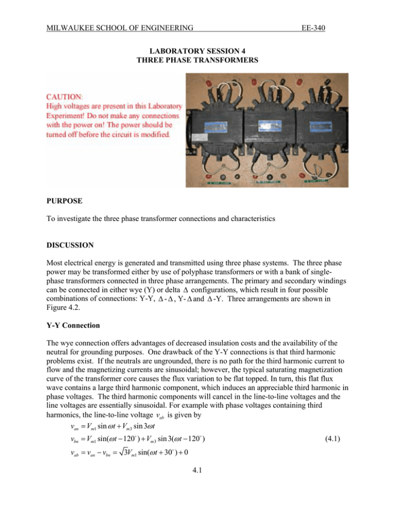
Three phase transformers
advertisement

MILWAUKEE SCHOOL OF ENGINEERING EE-340 LABORATORY SESSION 4 THREE PHASE TRANSFORMERS PURPOSE To investigate the three phase transformer connections and characteristics DISCUSSION Most electrical energy is generated and transmitted using three phase systems. The three phase power may be transformed either by use of polyphase transformers or with a bank of singlephase transformers connected in three phase arrangements. The primary and secondary windings can be connected in either wye (Y) or delta ∆ configurations, which result in four possible combinations of connections: Y-Y, ∆ - ∆ , Y- ∆ and ∆ -Y. Three arrangements are shown in Figure 4.2. Y-Y Connection The wye connection offers advantages of decreased insulation costs and the availability of the neutral for grounding purposes. One drawback of the Y-Y connections is that third harmonic problems exist. If the neutrals are ungrounded, there is no path for the third harmonic current to flow and the magnetizing currents are sinusoidal; however, the typical saturating magnetization curve of the transformer core causes the flux variation to be flat topped. In turn, this flat flux wave contains a large third harmonic component, which induces an appreciable third harmonic in phase voltages. The third harmonic components will cancel in the line-to-line voltages and the line voltages are essentially sinusoidal. For example with phase voltages containing third harmonics, the line-to-line voltage vab is given by van = Vm1 sin ω t + Vm3 sin 3ω t vbn = Vm1 sin(ω t − 120D ) + Vm 3 sin 3(ω t − 120D ) vab = van − vbn = 3Vm1 sin(ω t + 30 ) + 0 D 4.1 (4.1) MILWAUKEE SCHOOL OF ENGINEERING EE-340 To eliminate the harmonics in phase voltages a third set of windings, called a tertiary winding, connected in ∆ is normally fitted on the core so that the required third harmonic component of the exciting current can be supplied. This tertiary winding can also supply an auxiliary load if necessary. If the source and both transformer neutrals are grounded, third harmonic currents can flow, thereby restoring a sinusoidal flux variation. In this case, all voltages are approximately sinusoidal (at fundamental frequency), but the third harmonic currents flow back to the source through the neutral ground. This can cause telephone or other related interference. This connection is rarely used because of harmonic magnetizing currents in the ground circuit. The relationships between the line and the phase voltages for the Y-Y connections are: VHL = 3VHP , VXL = 3VXP ⇒ VHL VHP N1 = = =a VXL VXP N 2 (4.2) The letters H and X represent high and low voltages, respectively, and the subscript L stands for line, and P stands for phase quantities. ∆ - ∆ Connection The ∆ connection provides no neutral connection and each transformer must withstand full lineto-line voltage. The ∆ connection does, however, provide a path for third harmonic currents to flow. This results in a sinusoidal flux waveform producing sinusoidal phase voltages. This connection has the advantage that one transformer can be removed for repair and the remaining two can continue to deliver three-phase power at a reduced rating of 58% of that of the original bank. This is known as the V connection. The relationships between the line and the phase voltages for the ∆ - ∆ connections are: VHL VHP N1 VHL = VHP , VXL = VXP ⇒ = = =a (4.3) VXL VXP N 2 Y- ∆ Connection The Y connection has no problem with third harmonic components in its voltages because the closed path provided by the secondary ∆ connection permits the third harmonic magnetizing current to exist. In turn, this currents act to virtually eliminate the third harmonic component in the flux wave, thus ensuring a sinusoidal flux wave producing sinusoidal phase voltages. The Y neutral is grounded to reduce the undesirable effects with unbalanced loads. This connection is commonly used to step down a high voltage to a lower voltage. VHL V N VHL = 3VHP , VXL = VXP ⇒ = 3 HP = 3 1 = 3a (4.4) VXL VXP N2 ∆ -Y Connection The ∆ -Y connection is the same as Y- ∆ , except that the primary and secondary are reversed. If the Y connection is used on ∆ the high voltage side, insulation costs are reduced. This 4.2 MILWAUKEE SCHOOL OF ENGINEERING EE-340 connection is commonly used for stepping up to a high voltage. The Y- ∆ and the ∆ -Y connections will result in a phase shift between the primary and secondary line-to-line voltages, with the low voltage lagging the high voltage by 30D as shown in Figure 4.1. Because of the phase shift inherent in Y- ∆ and ∆ -Y banks, they must not be paralleled with Y-Y, ∆ - ∆ , or V-V banks VCN VAB Vca 30D VAN Vab Vbc VBN Y-connected HV side ∆ -connected LV side Figure 4.1 Phase shift in line-to-line voltages in a Y- ∆ connection 4.3 MILWAUKEE SCHOOL OF ENGINEERING Three-phase 208 V Supply B A H1 H1 H2 EE-340 C H2 H1 H2 N A b B a N a X1 X2 b X1 X2 c n X1 X2 n c C (a) Y-Y connection Three-phase 208 V Supply B A H1 H1 H2 C H2 H1 N H2 A c B N a X1 X2 b X1 X2 c X1 X2 C b a (b) Y-∆ connection Three-phase 208 V Supply B A H1 a X1 H2 X2 H1 b X1 C H2 X2 H2 H1 c X1 X2 A c B b C a (c) ∆-∆ connection Figure 4.2 Three-phase connections of single-phase transformers 4.4 MILWAUKEE SCHOOL OF ENGINEERING EE-340 PROCEDURE 1. Y-Y Connection (a) Line and phase RMS voltage Measurements − Connect the single-phase transformers Y-Y as shown in Figure 4.2 (a). Connect the high voltage winding to the three-phase 208 V power supply. Turn the power on and using a DMM measure the primary line-to-neutral voltages. You don't need to connect voltmeters permanently in the circuit. To measure the phase voltages connect the lead coming from the black terminal of the voltmeter to the neutral and carefully holding the lead coming from the voltmeter red terminal move from one phase to the next and measure the phase voltages (if slightly different consider a mean value for VHP ); also measure the primary line-to-line voltages VHL . Repeat these measurements for the secondary side and measure VXP and VXL . Record in Table I. (b) Turn on the PC and load the Fluke View ScopeMeter software. With both Y neutrals isolated connect the ScopeMeter input A to one phase of the secondary terminal X1 and COM terminal to the secondary neutral. Turn on the ScopeMeter. Turn on input A to measure RMS voltage and make sure input A is selected for triggering. Press Auto to display the secondary line to neutral voltage. Click on the Display Waveforms icon to open its dialog box and check mark Acquisition Memory A to display the secondary line-to-neutral voltage. Select Tool/Spectrum to create and display the voltage spectrum. Record the frequency, values in volt and the percent for fundamental, and up to the 7th harmonics. Save the voltage waveform and its spectrum graphs as a bitmap graphic (*.bmp) file on your F drive for inclusion in your report. Also, save the voltage traces with extension FVF, this way you can retrieve them again using Fluke software. Connect the ScopeMeter input A and COM to the secondary line-to-line terminals. Click on the Display Waveforms icon to open its dialog box and check mark Acquisition Memory A to display and save the secondary line-to-line voltage and its spectrum. (c) Connect the secondary neutral to the primary neutral and ground the neutrals. (You can find a ground terminal, a green plug on the right side of the AC supply box located behind your bench). Connect Input A and COM to measure the secondary line to neutral voltage. Turn on the ScopeMeter and click on the Display Waveforms icon to open its dialog box and check mark Acquisition Memory A to display the secondary line-to-neutral voltage. Obtain the voltage spectrum. Is there any appreciable harmonics in the line-to-neutral voltage? Save these waveforms. Connect Input A and COM to measure the secondary line-to-line voltage and observe the harmonics content if any. TURN OFF THE POWER SUPPLY EACH TIME BEFORE YOU RECONNECT THE LEADS 4.5 MILWAUKEE SCHOOL OF ENGINEERING EE-340 2. Y- ∆ Connection (a) Line and phase RMS voltage Measurements − Reconnect the single-phase transformers Y∆ as shown in Figure 4.2(b). Connect the high voltage winding to the three-phase 208 V power supply. Turn the power on and using a DMM measure the primary line-to-neutral voltages (if slightly different consider a mean value for VHP ) also measure the primary line-to-line voltages VHL . Repeat these measurements for the secondary side and measure VXP = VXL . Record in Table I. Turn the power on and using a DMM record the primary and secondary line-to-line and line-to neutral voltages in Table I. (b) Connect the ScopeMeter input A and COM to measure the phase voltage of one phase of the ∆ connected secondary. Examine the voltage spectrum for its harmonic contents. There should be negligible third harmonic component in the phase voltages whether the primary neutral is grounded or isolated. Ground the primary neutral and investigate. (c) Ground the Y neutral. Open one side of ∆ (i.e., connection between two secondary windings) and insert the ScopeMeter input A and COM to measure the open loop voltage. Turn on the ScopeMeter. Measure the secondary open-loop voltage VLOOP = _________________________ With the primary neutral grounded, third harmonic magnetization current can flow in the primary resulting in sinusoidal secondary voltages, thus the secondary open-loop voltage measured should be approximately zero. (d) Isolate the primary neutral. With Y-neutral not grounded and ScopeMeter connected as in part (c) in the open delta turn the power on and record the open loop voltage. VLOOP( rms ) = _________________________ f = _________________________ Click on the Display Waveforms icon to open its dialog box and check mark Acquisition Memory A to display the secondary open-loop voltage Obtain the waveforms spectrum. Record the value in volts and percent and the frequency of the fundamental and up to the 7th harmonics. Save these waveforms. When the primary neutral is not grounded the primary currents are essentially sinusoidal (No path for the third-harmonics current to flow). However, the flux because of the nonlinear B-H characteristics of the magnetic core is nonsinusoidal and contains odd harmonics, in particular third harmonics. The phase voltages are therefore nonsinusoidal, containing fundamental and third harmonic voltages, with instantaneous values given by 4.6 MILWAUKEE SCHOOL OF ENGINEERING EE-340 van = Vm1 sin ω t + Vm3 sin 3ω t vbn = Vm1 sin(ω t − 120D ) + Vm 3 sin 3(ω t − 120D ) (4.5) vcn = Vm1 sin(ω t − 240D ) + Vm 3 sin 3(ω t − 240D ) Note that fundamental phase voltages are phase shifted by 120D from each other, whereas third harmonic voltages are all in phase. The open loop voltage around delta is the sum of phase voltages. The sum of fundamental components is zero, whereas the third harmonics will add up. The result is VLOOP = Van + Vbn + Vcn = 3Vm3 sin 3ω t (4.6) Note that when the secondary delta is closed, it permits the third harmonic current to flow in the secondary delta restoring sinusoidal flux and sinusoidal phase voltages as seen in part 2(b). 3. ∆ - ∆ Connection (a) Line and phase RMS voltage Measurements − Reconnect the single-phase transformers ∆ - ∆ as shown in Figure 4.2(c). Connect the high voltage winding to the three-phase 208 V power supply. Turn the power on and using a DMM measure the primary line-to-line voltages VHL = VHP . Repeat these measurements for the secondary side and measure VXP = VXL . Record in Table I. (b) Connect the ScopeMeter input A and COM to measure the phase voltage of one phase of the ∆ connected secondary. Examine the voltage spectrum for its harmonic contents. (c) Open one side of the secondary ∆ (i.e., connection between two secondary windings) and insert the ScopeMeter input A and COM to measure the open loop voltage. Turn on the ScopeMeter. Measure the secondary open-loop voltage VLOOP = _________________________ The ∆ - ∆ connection provide a path for third harmonic currents to flow and therefore the phase voltages will not contain third harmonics. Thus, with identical transformers, the phase voltages are balanced and VLOOP should be zero or small. 4.7 MILWAUKEE SCHOOL OF ENGINEERING EE-340 Table I High voltage Measurements Transformer (L-N) connections (L-L) VHL VHP Low-voltage Measurements (L-L) (L-n) VXL VXP Line to phase ratio VHL VXL VHP VXP Prim. to sec. ratio VHL VHP VXL VXP Wye-Wye Wye-Delta Delta-Delta Using the measured voltages determine the above ratios in Table I. 4. Improper Y connections Connect the single-phase transformers Y-Y with connection to one phase of secondary (say phase a) reversed as shown in Figure 4.3. Three-phase 208 V Supply A B C H1 H2 H1 H2 H1 X1 X2 X1 X2 X1 c b Figure 4.3 Improper Y-Y connections a H2 N n X2 Turn the power on and record all three secondary line-to- line and line-to-neutral voltages. Van = _________________________ Vbn = _________________________ Vcn = _________________________ Vab = _________________________ Vbc = _________________________ Vca = _________________________ For the above connections from Kirchhoff's voltage law the secondary line-to-line voltages are given by 4.8 MILWAUKEE SCHOOL OF ENGINEERING EE-340 Vcn Vab Vca 120D Vab = Van − Vbn = VXP ∠180D − VXP ∠ − 120D = VXP ∠120D Vbc = Vbn − Vcn = VXP ∠ − 120D − VXP ∠120D = 3VXP ∠ − 90D Van 60D 90D Vca = Vcn − Van = VXP ∠120D − VXP ∠180D = VXP ∠60D Vbn (4.7) Vbc Figure 4.4 Phasor diagram for Improper Y connection. 5. Improper delta connection In the ∆ - ∆ arrangement, reverse the connection of one phase of the secondary winding (say phase a). Open the secondary delta (connection between two secondary windings) and insert a voltmeter to read the open loop voltage as shown in Figure 4.5. Three-phase 208 V Supply B A H1 H2 H1 C H2 H1 Vca H2 VLOOP a X2 X1 V X1 b X2 c X1 X2 Vab Vbc Figure 4.5 The improper ∆ connection. CAUTION: COMPLETE THE CIRCUIT FOR IMPROPER ∆ THROUGH A VOLTMETER DO NOT ENERGIZE THE IMPROPER ∆ UNLESS YOU HAVE INSERTED A VOLTMETER IN THE LOOP. 4.9 MILWAUKEE SCHOOL OF ENGINEERING EE-340 Turn the power on and record the open loop voltage. VLOOP = _________________________ Neglecting harmonics, voltage around the open delta is given by VLOOP = Van + Vbn + Vcn = VXP ∠180D + VXP ∠ − 120D + VXP ∠ − 240D = 2VXP ∠180D (4.8) REPORT REQUIREMENTS 1. Draw a phasor diagram showing the primary and secondary line-to-line and line-to neutral voltages for the Y-Y, ∆ - ∆ , and Y- ∆ connections. For the Y- ∆ connections determine the phase shift between the primary and secondary line-to-line voltages. Enumerate the necessary conditions for parallel operation of two three-phase transformers. 2. Using relations (4.2-4.4) calculate the voltage ratios and record in Table I. Compare with the measured values. What does the ratio of line-to-line to line-to-neutral voltage for Y connections in Table I demonstrate? 3. The ratios of primary to secondary phase or line voltages are all approximately equal for all connections in Table I except for the Y connection. Why? 4. What are the problems associated with the Y-Y three-phase transformer connection? Discuss the harmonics in the Y-Y connection and the observation made in parts 1(b) and 1(c). With isolated neutrals does the phase voltages contain third harmonics? Are there third harmonic in the line-to-line voltages (see equation 4.1). 5. Discuss the observation made in part 2(b). Is there any third harmonic component in the secondary of the Y- ∆ connection? What is the value of the open loop voltage measured in part 2(c)? Is this value approximately zero with the Y neutral grounded? Is this value zero with the Y neutral ungrounded part 2(d)? If not, what does it represent and what is the approximate frequency of this voltage? What is the rms magnitude of the third-harmonic phase voltage of the secondary when third-harmonic voltages are present? 6. Discuss the observation made in part 3(b). Is there any third harmonic component in the secondary voltage of the ∆ - ∆ connection? What is the value of the open loop voltage measured in part 3(c)? Is this value approximately zero? 7. For the improper Y -Y connection of part 4, use (4.7) to compute the line voltages and compare with the measured values. Are the line voltages symmetrical? 8. For the improper ∆ connection of part 5, use (4.8) to compute the open loop voltage and compare with the measured value. Is this an appropriate ∆ connection? Why? 9. In a ∆ - ∆ connections can one of the transformers be removed with the remaining ones operating satisfactorily why? What is the name of this connection? 4.10


