G3 Electronics
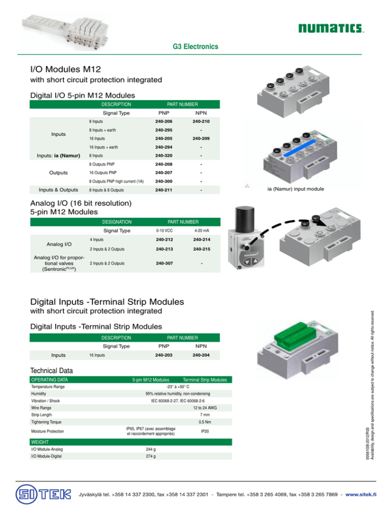
I/O Modules M12
with short circuit protection integrated
Digital I/O 5-pin M12 Modules
DESCRIPTION
PART NUMBER
Signal Type
Inputs
Inputs: ia (Namur)
Outputs
Inputs & Outputs
PNP
NPN
8 Inputs
240-206
240-210
8 Inputs + earth
240-295
-
16 Inputs
240-205
240-209
16 Inputs + earth
240-294
-
8 Inputs
240-320
-
8 Outputs PNP
240-208
-
16 Outputs PNP
240-207
-
8 Outputs PNP high current (1A)
240-300
-
8 Inputs & 8 Outputs
240-211
-
ia (Namur) input module
Analog I/O (16 bit resolution)
5-pin M12 Modules
DESIGNATION
PART NUMBER
Signal Type
Analog I/O
Analog I/O for proportional valves
(SentronicPLUS)
0-10 VCC
4-20 mA
4 Inputs
240-212
240-214
2 Inputs & 2 Outputs
240-213
240-215
2 Inputs & 2 Outputs
240-307
-
with short circuit protection integrated
Digital Inputs -Terminal Strip Modules
DESCRIPTION
PART NUMBER
Signal Type
Inputs
16 Inputs
PNP
NPN
240-203
240-204
Technical Data
OPERATING DATA
5-pin M12 Modules
Temperature Range
Humidity
Vibration / Shock
Terminal Strip Modules
-23° à +50° C
95% relative humidity, non-condensing
IEC 60068-2-27, IEC 60068-2-6
Wire Range
12 to 24 AWG
Strip Length
7 mm
Tightening Torque
0.5 Nm
Moisture Protection
IP65, IP67 (avec assemblage
et raccordement appropriés)
WEIGHT
I/O Module-Analog
244 g
I/O Module-Digital
274 g
IP20
00561GB-2012/R03
Availability, design and specifications are subject to change without notice. All rights reserved.
Digital Inputs -Terminal Strip Modules
G3 Electronics
I/O Modules M12
RTD temperature sensor input module
Analog I/O (16 bit resolution)
5-pin M12 Modules
DESIGNATION
ORDER CODE
Analog I/O 4 Inputs
consult us
OPERATING DATA
RTD temperature sensor input module
Temperature range (ambient)
-20° à +46° C
Humidity
95% relative humidity, non-condensing
Vibration / Shock
IEC 60068-2-27, IEC 60068-2-6
Sensor type of input
Pt100 - Pt200 - Pt500 - Pt1000
Sensor connection technology
Temperature range of input signal
-200°C to +850°C
Minimum temperature scale
25°C
Moisture protection
IP65, IP67 with appropriate assembly and termination
Absolute accuracy at +25°C
0,03% (linearity / repeatability / hysteresis / stability)
Temperature error relatives to input range
ATEX certification
Standard
Ni100 - Ni120 - Ni500 - Ni1000
2-3-4 wires (3 wires with compensation of connection cable)
+/- 0,05%
compatible to zone 2-22 and sensor installed in zone 2-22
DIN/IEC 60751, IEC 751, DIN 43710
Module weight
244g
I/O Modules / cables & connectors
00561GB-2011/R01
Availability, design and specifications are subject to change without notice. All rights reserved.
Accessory
Description
Order Code
5 pin straight male M12 connector
88100330
5 pin elbow male M12 connector
88161927
230-647
Dust Cover - M12 Male
5 pin male DUO M12 connector for 2 inputs
(2 cables, Ø3-5 mm)
M12 SPEEDCON connector Straight
4 Pin Male Single Ended Cable,
Euro Color Code
M12 SPEEDCON connector 90° 4 Pin Male Single
Ended Cable,
Euro Color Code
Replacement Terminal strip
Keying Element for terminal strip
www.asconumatics.eu
88100253
1,5 m
TA04E5MIE000071P
3m
TA0403MIE000071P
5m
TA0405MIE000071P
1,5 m
TB04E5MIE000071P
3m
TB0403MIE000071P
5m
TB0405MIE000071P
I/O 0-7
140-1073
I/O 8-15
140-1074
140-1076
57
G3 Electronics
G3 Platform Distribution Options
Easy, Cost Effective Solutions for Digital I/O and Valve Automation using G3 Electronics
• ➆
• ➁
• ➃ • ➇
Main Fieldbus Island
Backplane extension
• ➁ • ➆
• ➂
Backplane
extension In
Backplane extension Out
24 VDC Power
Supply (optional for
input modules)
I/O Only
Distributed Island
with Valves
• ➆
• ➁• ➀• ➇
Distributed Island
with I/O & Valves
Backplane
extension Out
24 VDC
Power
Supply
Backplane
extension
• ➀
• ➇
24 VDC
Power
Supply
• Unique distribution system allows system efficiency by allowing the same
modules to be used in either centralized or distributed applications
• Distribution options include:
Inputs OR Outputs
Inputs AND Outputs
Valves with Inputs AND Outputs
Valves with Inputs OR Outputs
Valves Only
•Maximum Backplane extension length not to exceed 30 meters.
Maximum Backplane extension cable current not to exceed 4 amps or excessive
cable voltage drops per segment. Auxiliary power connections available for currents
above 4 amps. Consult factory for possible deviations.
58
00561GB-2012/R03
Availability, design and specifications are subject to change without notice. All rights reserved.
• ➅
• ➆
G3 Electronics
N°
Weight
Part
number
235g
240-241
with DIN
Rail Clips
141g
240-244
W/o clips
130g
240-183
with DIN
Rail Clips
141g
240-246
W/o clips
130g
240-185
127g
240-182
127g
240-186
with DIN
Rail Clips
102g
240-245
W/o clips
91g
240-184
45g
240-179
with DIN
Rail Clips
147g
P599AE425188002
W/o clips
136g
P599AE425188001
Description
Accessories
Backplane Extension Modules
➀
Distributed
Valve Module
Distributed module for valves with
display
➁
G3 Backplane
extension Left
End Module
G3 Left End Module for backplane
distribution and 24VDC to I/O modules
➂
G3 Backplane
extension
Right Module
G3 Right Module allowing the connection of distributed I/O modules
Miscellaneous Modules
➃
Auto Recovery
Module (ARM)
Protects configuration information
during a critical failure. Allows
configuration information to be saved
and reloaded to replacement module
automatically.
➄
Manual
Configuration
Module (MCM)
An optional module to set configuration parameters by dip switches
(i.e. node address)
➅
G3 Left
Terminator
Module
Must be installed after the last I/O
module or after the communication
module if there are no I/O modules
installed.
00561GB-2013/R01
Availability, design and specifications are subject to change without notice. All rights reserved.
➆
➇
➈
Jumper Clip
Valve Driver
Module
Right Hand
Mounting
Cover
Provides electrical connections
between modules
G3 electrical interface to pneumatics
ends and valves
Used when a communication module
is used without local valves installed
with DIN
Rail Clips
240-289
W/o clips
240-255
Accessories
Labels
M12
Dust Cover
For use with Murrplastik© Type 20 Software
Male
122-1251
230-647
Protects the connector against dust
Female
www.asconumatics.eu
88157773
59
G3 Electronics
Example Backplane extension Layout and Cabling (DeviceNet™ / CANopen®
Network)
C
Power Supply
A
A
D
Cable
60
Description
Example Cable Part #
Power Cable
MC0405MAC0000000
DeviceNet/CANopen® Communication Cable
MC0505MGD0000000
Backplane extension Cable
TA0501MGDTC0571P
Alternate Backplane extension Power Option
TA0401MA0MC04000
I/O Field Wireable Connector
TA04F2000000081E
I/O Connector with Molded Cable
TA0405MIE000071P
00561GB-2012/R03
Availability, design and specifications are subject to change without notice. All rights reserved.
B
G3 Electronics
Accessory
Description
Order Code
M12 Backplane extension cables with SPEEDCON connector technology
A
M12 Straight 5 Pin Male to Female Backplane extension Cable - Shielded
(backplane extension)
1m
TA0501MGDTC0571P
5m
TA0505MGDTC0571P
10m
TA0510MGDTC0571P
7/8” MINI 4 Pin cables & connectors for backplane extension valve module power
7/8” MINI Straight 4 Pin Female Single
Ended Cable, Euro Color Code
7/8” MINI 90° 4 Pin Female Single Ended
Cable, Euro Color Code
5m
MC0405MAC0000000
10m
MC0410MAC0000000
5m
MD0405MAC0000000
10m
MD0410MAC0000000
Male View
1
2
3
4
B
7/8” MINI Straight 4 Pin Female Field Wireable Connector –Cable Gland – One size
fits all
230-1003
7/8” MINI 90° 4 Pin Female Field Wireable Connector – PG 9 Cable Gland
230-1001
00561GB-2013/R01
Availability, design and specifications are subject to change without notice. All rights reserved.
M12 4 Pin cables for backplane extension In/Out module power
C
M12 to 7/8” MINI Cable for Backplane extension Power
M12 Straight 4 Pin Male to 7/8” MINI 4 Pin Female Extension
(distribution of the power 24V to valve islands)
M12 Straight 4 Pin Male to Female Cable Extension
D
M12 Cables for Backplane extension Power
M12 Straight 4 Pin Female Single Ended
Cable, Euro Color Code
M12 Cables for Backplane extension Power
M12 90° 4 Pin Female Single Ended Cable,
Euro Color Code
1m
TA0401MA0MC0471T
5m
TA0405MA0MC0471T
10m
TA0410MA0MC0471T
1m
TC0401MAETA04000
5m
TC0405MAETA04000
10m
TC0410MAETA04000
5m
TC0405MAE0000000
10m
TC0410MAE0000000
5m
TD0405MAE0000000
10m
TD0410MAE0000000
Male View
1
2
3
4
www.asconumatics.eu
61
G3 Electronics
Dimensional Drawing - G3 Fieldbus Island Assembly
503 series valve island assembly with G3 Electronics w/ Backplane extension Output
Clearance holes for
M5 or #10 screws
6,3 wide slot
(2) places
M
L
B
E
D
C
A
For use with
optional DIN rail
hardware
G
H
J
K
AD
Y
AA
X
P
Q
N
AB
W
Z
AC
F
R
S
T
U
V
Dimensions (in mm)
A
B
C
D
E
F
G
H
J
K
L
M
N
P
Q
R
S
T
U
105,5
6,3
38
52,8
33,8
7
57,5
67,5
71,7
157,4
39,1
75,8
68,1
56,3
54
24,8
67,5
36,9
221,3
V
W
X
Y
Z
AA
AB
AC
AD
368,6
12,5
24,8
53
54
55,1
101,1
112,9
207
F
46,3
H
J
K
195,1
Y
AA
P
Q
N
13,5
S
T
210,2
359,4
62
AC
X
AB
W
Z
00561GB-2012/R03
Availability, design and specifications are subject to change without notice. All rights reserved.
M
L
B
E
D
C
A
503 series valve island assembly with G3 Electronics w/o backplane extension output
(with left terminator module)
G3 Electronics
Dimensional Drawing - G3 Fieldbus I/O Assembly
I/O Assembly with G3 Electronics w/o Backplane extension output
FOR USE WITH
OPTIONAL
DIN RAIL HARDWARE
E
F
G
H
ADDITIONAL MOUNTING HOLES (4)
FOR USE WITH M5 OR #10 SCREWS
D
A
B
C
P
R
N
K
L
S
M
T
U
J
VIEW SHOWN WITH OPTIONAL DIN
RAIL HARDWARE AND 35mm DIN
RAIL
I/O Assembly with G3 Electronics w/ Backplane extension output
FOR USE WITH
OPTIONAL
DIN RAIL HARDWARE
00561GB-2011/R01
Availability, design and specifications are subject to change without notice. All rights reserved.
E
F
G
H
ADDITIONAL MOUNTING HOLES (4)
FOR USE WITH M5 OR #10 SCREWS
A1
D
B
C
P
R
N
K1
L
S
M
T
U
J1
VIEW SHOWN WITH OPTIONAL DIN
RAIL HARDWARE AND 35mm DIN
RAIL
Dimensions (in mm)
A
A1
B
C
D
E
F
G
H
46,4
57,6
67,5
57,6
7,0
105,5
38,0
33,7
6,25
J
J1
185,3 196,5
K
K1
L
M
N
P
R
S
T
U
13,5
24,5
67,5
37
54,0
12,5
62,5
5,1
59,0
118,0
www.asconumatics.eu
63

