A72 Series Two-Pole Heavy Duty Temperature
advertisement
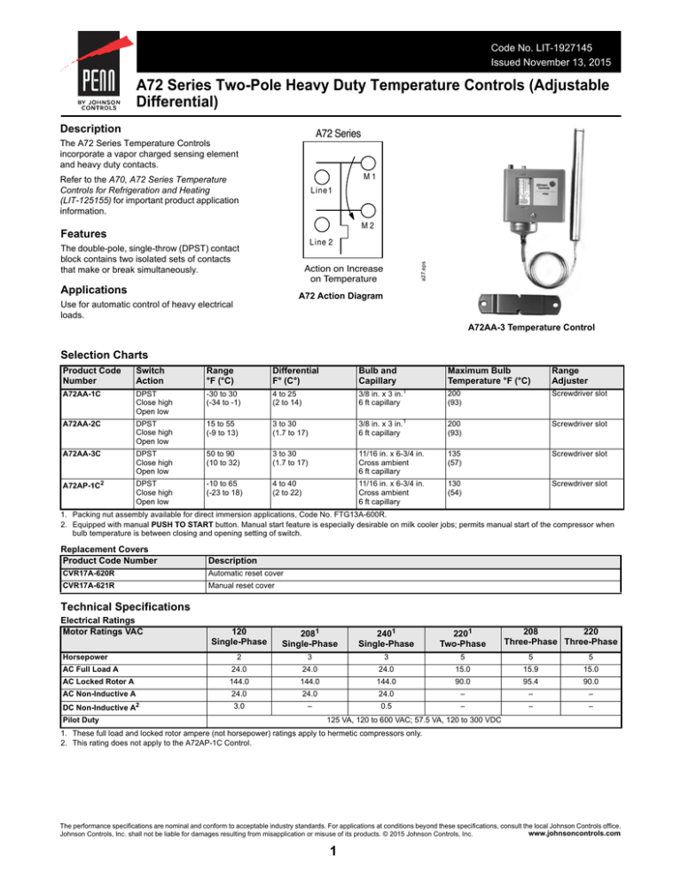
Code No. LIT-1927145 Issued November 13, 2015 A72 Series Two-Pole Heavy Duty Temperature Controls (Adjustable Differential) Description A72 Series The A72 Series Temperature Controls incorporate a vapor charged sensing element and heavy duty contacts. Refer to the A70, A72 Series Temperature Controls for Refrigeration and Heating (LIT-125155) for important product application information. M1 L ine 1 M2 Features a27.eps L ine 2 The double-pole, single-throw (DPST) contact block contains two isolated sets of contacts that make or break simultaneously. Action on Increase on Temperature Applications A72 Action Diagram Use for automatic control of heavy electrical loads. A72AA-3 Temperature Control Selection Charts Product Code Number Switch Action Range °F (°C) Differential F° (C°) Bulb and Capillary Maximum Bulb Temperature °F (°C) Range Adjuster A72AA-1C DPST Close high Open low -30 to 30 (-34 to -1) 4 to 25 (2 to 14) 3/8 in. x 3 in.1 6 ft capillary 200 (93) Screwdriver slot A72AA-2C DPST Close high Open low 15 to 55 (-9 to 13) 3 to 30 (1.7 to 17) 3/8 in. x 3 in.1 6 ft capillary 200 (93) Screwdriver slot A72AA-3C DPST Close high Open low 50 to 90 (10 to 32) 3 to 30 (1.7 to 17) 11/16 in. x 6-3/4 in. Cross ambient 6 ft capillary 135 (57) Screwdriver slot A72AP-1C2 DPST Close high Open low -10 to 65 (-23 to 18) 4 to 40 (2 to 22) 11/16 in. x 6-3/4 in. Cross ambient 6 ft capillary 130 (54) Screwdriver slot 1. Packing nut assembly available for direct immersion applications, Code No. FTG13A-600R. 2. Equipped with manual PUSH TO START button. Manual start feature is especially desirable on milk cooler jobs; permits manual start of the compressor when bulb temperature is between closing and opening setting of switch. Replacement Covers Product Code Number Description CVR17A-620R Automatic reset cover CVR17A-621R Manual reset cover Technical Specifications Electrical Ratings Motor Ratings VAC Horsepower 120 Single-Phase 2081 Single-Phase 2401 Single-Phase 2201 Two-Phase 208 220 Three-Phase Three-Phase 2 3 3 5 5 5 AC Full Load A 24.0 24.0 24.0 15.0 15.9 15.0 AC Locked Rotor A 144.0 144.0 144.0 90.0 95.4 90.0 AC Non-Inductive A 24.0 24.0 24.0 – – – DC Non-Inductive A2 3.0 – 0.5 – – – Pilot Duty 125 VA, 120 to 600 VAC; 57.5 VA, 120 to 300 VDC 1. These full load and locked rotor ampere (not horsepower) ratings apply to hermetic compressors only. 2. This rating does not apply to the A72AP-1C Control. The performance specifications are nominal and conform to acceptable industry standards. For applications at conditions beyond these specifications, consult the local Johnson Controls office. www.johnsoncontrols.com Johnson Controls, Inc. shall not be liable for damages resulting from misapplication or misuse of its products. © 2015 Johnson Controls, Inc. 1
