EXPERIMENT 5 Problem Solving: Nodal and Mesh Analysis
advertisement

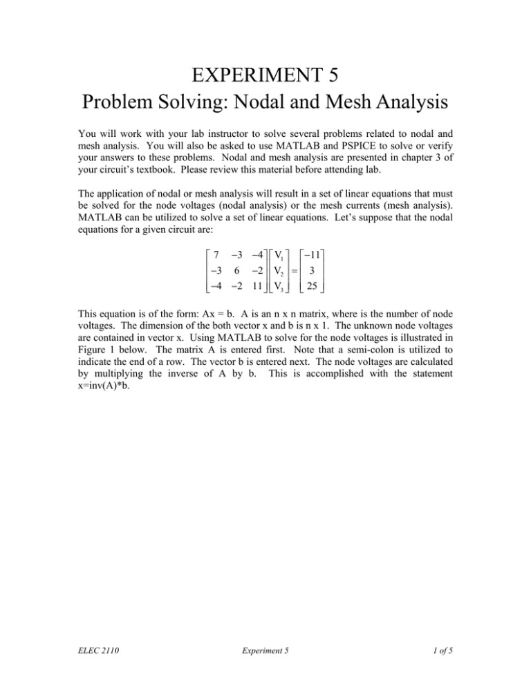
EXPERIMENT 5 Problem Solving: Nodal and Mesh Analysis You will work with your lab instructor to solve several problems related to nodal and mesh analysis. You will also be asked to use MATLAB and PSPICE to solve or verify your answers to these problems. Nodal and mesh analysis are presented in chapter 3 of your circuit’s textbook. Please review this material before attending lab. The application of nodal or mesh analysis will result in a set of linear equations that must be solved for the node voltages (nodal analysis) or the mesh currents (mesh analysis). MATLAB can be utilized to solve a set of linear equations. Let’s suppose that the nodal equations for a given circuit are: ⎡ 7 −3 −4 ⎤ ⎡ V1 ⎤ ⎡ −11⎤ ⎢ −3 6 −2 ⎥ ⎢ V ⎥ = ⎢ 3 ⎥ ⎢ ⎥⎢ 2⎥ ⎢ ⎥ ⎢⎣ −4 −2 11 ⎥⎦ ⎢⎣ V3 ⎥⎦ ⎢⎣ 25 ⎥⎦ This equation is of the form: Ax = b. A is an n x n matrix, where is the number of node voltages. The dimension of the both vector x and b is n x 1. The unknown node voltages are contained in vector x. Using MATLAB to solve for the node voltages is illustrated in Figure 1 below. The matrix A is entered first. Note that a semi-colon is utilized to indicate the end of a row. The vector b is entered next. The node voltages are calculated by multiplying the inverse of A by b. This is accomplished with the statement x=inv(A)*b. ELEC 2110 Experiment 5 1 of 5 Figure 1. Solution of a set of linear equations using MATLAB. ELEC 2110 Experiment 5 2 of 5 Exercises For all exercises, include in your report circuit diagrams with all variables clearly labeled. Also, include the nodal and mesh equations written for each circuit. 1) Write nodal equations for the circuit below and solve for V0. Use MATLAB to solve your equations. Repeat using mesh analysis. Simulate the circuit in PSPICE to check your answer. Include in your report a screenshot of the schematic with V0 displayed on that schematic. 2) Write nodal equations for the circuit below and solve for V0. Use MATLAB to solve your equations. Repeat using mesh analysis. Simulate the circuit in PSPICE to check your answer. Include in your report a screenshot of the schematic with V0 displayed on that schematic. ELEC 2110 Experiment 5 3 of 5 3) Write nodal equations for the circuit below and solve for V0. Use MATLAB to solve your equations. Repeat using mesh analysis. Simulate the circuit in PSPICE to check your answer. Include in your report a screenshot of the schematic with V0 displayed on that schematic. 4) Write nodal equations for the circuit below and solve for V0. Use MATLAB to solve your equations. Repeat using mesh analysis. Simulate the circuit in PSPICE to check your answer. Include in your report a screenshot of the schematic with V0 displayed on that schematic. ELEC 2110 Experiment 5 4 of 5 5) Write nodal equations for the circuit below and solve for V2. Use MATLAB to solve your equations. Repeat using mesh analysis. Simulate the circuit in PSPICE to check your answer. Include in your report a screenshot of the schematic with V2 displayed on that schematic. Also calculate the power supplied by the dependent current source. 6) Write nodal equations for the circuit below and solve for I0. Use MATLAB to solve your equations. Repeat using mesh analysis. Simulate the circuit in PSPICE to check your answer. Include in your report a screenshot of the schematic with I0 displayed on that schematic. Also calculate the power supplied by the dependent current source. ELEC 2110 Experiment 5 5 of 5

