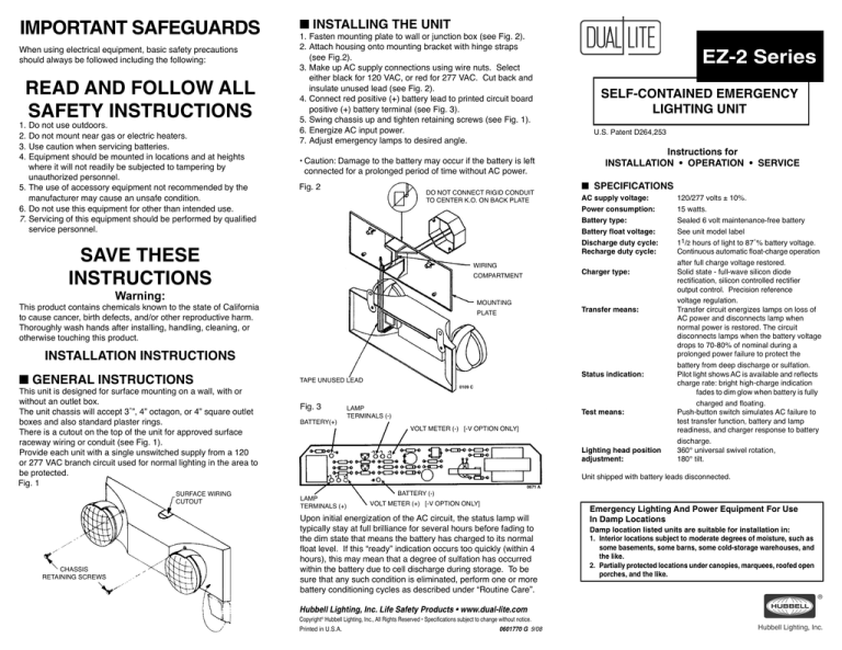
IMPORTANT SAFEGUARDS
When using electrical equipment, basic safety precautions
should always be followed including the following:
READ AND FOLLOW ALL
SAFETY INSTRUCTIONS
1.Do not use outdoors.
2.Do not mount near gas or electric heaters.
3.Use caution when servicing batteries.
4.Equipment should be mounted in locations and at heights where it will not readily be subjected to tampering by unauthorized personnel.
5.The use of accessory equipment not recommended by the
manufacturer may cause an unsafe condition.
6.Do not use this equipment for other than intended use.
7.Servicing of this equipment should be performed by qualified
service personnel.
■ INSTALLING THE UNIT
1.Fasten mounting plate to wall or junction box (see Fig. 2).
2.Attach housing onto mounting bracket with hinge straps
(see Fig.2).
3.Make up AC supply connections using wire nuts. Select either black for 120 VAC, or red for 277 VAC. Cut back and insulate unused lead (see Fig. 2).
4.Connect red positive (+) battery lead to printed circuit board positive (+) battery terminal (see Fig. 3).
5.Swing chassis up and tighten retaining screws (see Fig. 1).
6.Energize AC input power.
7.Adjust emergency lamps to desired angle.
•Caution:Damage to the battery may occur if the battery is left connected for a prolonged period of time without AC power.
Fig. 2
DO NOT CONNECT RIGID CONDUIT
TO CENTER K.O. ON BACK PLATE
SAVE THESE
INSTRUCTIONS
WIRING
COMPARTMENT
Warning:
MOUNTING
This product contains chemicals known to the state of California
to cause cancer, birth defects, and/or other reproductive harm.
Thoroughly wash hands after installing, handling, cleaning, or
otherwise touching this product.
PLATE
INSTALLATION INSTRUCTIONS
■ GENERAL INSTRUCTIONS
This unit is designed for surface mounting on a wall, with or
without an outlet box.
The unit chassis will accept 3˚”, 4” octagon, or 4” square outlet
boxes and also standard plaster rings.
There is a cutout on the top of the unit for approved surface
raceway wiring or conduit (see Fig. 1).
Provide each unit with a single unswitched supply from a 120
or 277 VAC branch circuit used for normal lighting in the area to
be protected.
Fig. 1
SURFACE WIRING
CUTOUT
CHASSIS
RETAINING SCREWS
TAPE UNUSED LEAD
Fig. 3
BATTERY(+)
0109 C
LAMP
TERMINALS (-)
VOLT METER (-) [-V OPTION ONLY]
EZ-2 Series
SELF-CONTAINED EMERGENCY
LIGHTING UNIT
U.S. Patent D264,253
Instructions for
INSTALLATION • OPERATION • SERVICE
■ SPECIFICATIONS
AC supply voltage:
120/277 volts ± 10%.
Power consumption:
15 watts.
Battery type:
Sealed 6 volt maintenance-free battery
Battery float voltage:
See unit model label
Discharge duty cycle:
11/2 hours of light to 87˚% battery voltage.
Recharge duty cycle:
Continuous automatic float-charge operation after full charge voltage restored.
Charger type:
Solid state - full-wave silicon diode rectification, silicon controlled rectifier output control. Precision reference voltage regulation.
Transfer means:
Transfer circuit energizes lamps on loss of AC power and disconnects lamp when normal power is restored. The circuit disconnects lamps when the battery voltage drops to 70-80% of nominal during a prolonged power failure to protect the battery from deep discharge or sulfation.
Status indication:
Pilot light shows AC is available and reflects charge rate: bright high-charge indication fades to dim glow when battery is fully charged and floating.
Test means:
Push-button switch simulates AC failure to test transfer function, battery and lamp readiness, and charger response to battery
discharge.
Lighting head position
360° universal swivel rotation,
adjustment:
180° tilt.
Unit shipped with battery leads disconnected.
LAMP
TERMINALS (+)
BATTERY (-)
0671 A
VOLT METER (+) [-V OPTION ONLY]
Upon initial energization of the AC circuit, the status lamp will
typically stay at full brilliance for several hours before fading to
the dim state that means the battery has charged to its normal
float level. If this “ready” indication occurs too quickly (within 4
hours), this may mean that a degree of sulfation has occurred
within the battery due to cell discharge during storage. To be
sure that any such condition is eliminated, perform one or more
battery conditioning cycles as described under “Routine Care”.
Hubbell Lighting, Inc. Life Safety Products • www.dual-lite.com
Copyright© Hubbell Lighting, Inc., All Rights Reserved • Specifications subject to change without notice.
Printed in U.S.A.
0601770 G 9/08
Emergency Lighting And Power Equipment For Use
In Damp Locations
Damp location listed units are suitable for installation in:
1. Interior locations subject to moderate degrees of moisture, such as some basements, some barns, some cold-storage warehouses, and the like.
2. Partially protected locations under canopies, marquees, roofed open porches, and the like.
TROUBLESHOOTING CHART
SYMPTOM
POSSIBLE CAUSE
Unit blows AC supply fuse/breaker. Unit connected to 277 VAC circuit, but 120 volt input lead used.
PROCEDURE
Check AC input connections. If wrong, correct connections and try unit again, but charger module will also probably have to be replaced.
Short in unit wiring or charger module.
Check wiring. If wiring OK but disconnecting black or red lead from transformer clears short, replace charger module.
No pilot light indication when AC on. Emergency lamps may be on.
Unit connected to 120 VAC circuit, but 277 volt input lead chosen.
Check AC input connections and correct if wrong.
No red pilot light indication when AC on.
Unit connected to 277 VAC circuit, but 120 volt input lead used.
Check AC input connections. If wrong, correct connections and try unit
again, but charger module will also probably have to be replaced.
Defective charger module.
Replace module.
Pressing test switch does not light
emergency lamp(s).
If red lamp was bright before test switch
pressed, battery voltage may be below cutoff threshold.
Allow battery to charge until red light dims, and then repeat test. Battery lead may be disconnected.
If red lamp was dim before test switch pressed and does not light emergency
lamps when pressed, lamp(s) defective.
If all battery and lamp circuits check OK, replace charger module.
Defective charger/transfer module.
Prior lamp indications OK, but unit Battery partially sulfated.
fails to give full 1˚ hours of emergency lighting.
Battery defective.
Full apparent recharge occurs too quickly (within ˚ hour after
discharge to low-voltage cutoff),
and unit won’t perform 1˚ hour
test as above.
Same as causes of preceding symptom.
■ ROUTINE CARE
The battery used in these models is sealed and requires no
maintenance, but will benefit from certain operating procedures.
During routine standby operation, charger output fluctuates only
slightly in floating the battery at its full-charge voltage. But after
an AC failure and subsequent battery discharge, charger output
increases greatly to recharge the battery as quickly as cell
temperature-rise and gas-cycling considerations permit. This
vigorous charging action also agitates the electrolyte and tends
to reverse physical and chemical changes that can slowly occur
in a battery that stands for long periods without cycling. It follows
that if power failures are infrequent, occasional deliberate cycling
may extend battery life.
■ TEST CYCLING
Every three months, if there has been no power failure, press
the unit test switch for at least 30 seconds. Before the switch is
pressed, the pilot light should be glowing dimly. When the switch
is pressed, the pilot light should become bright and remain bright
when the switch is released (assuming that the emergency lights lit
while the switch was depressed). The pilot light should fade back
to its dim state within a few minutes.
Perform conditioning cycle(s) per instructions under Routine Care until short apparent recharge time symptom of sulfation no longer occurs.
■ EMERGENCY LAMP: REPLACE
1. To remove the lamp assembly from the lamp housing, place a screwdriver into the slot (Fig. 4), and pry the lamp assembly out.
2. Insert a screwdriver into the lens slot (Fig. 5) and pry the lens from the reflector assembly.
3. Remove the defective bulb (Fig. 6). Insert a new bulb into the reflector by aligning bulb base with socket and pushing lamp firmly into socket.
4. Reassemble the lamp:
a. align the small “key”, located between the anti-
rotation tabs on the reflector assembly, with the
“keyway” adjacent to the ribbed area on the edge of the lens. (Fig. 6).
b. press the lens into the reflector assembly.
5. Rejoin lamp assembly to lamp housing:
a. orient the lamp assembly’s anti-rotation tabs to the top of the lamp housing.
b. set the bottom of the lamp assembly into the housing and dress wires neatly into the housing cavity.
c. insert a screwdriver into the slot (Fig. 4) and lever the lamp assembly into the housing.
Fig. 4
INSERT SCREWDRIVER
INTO SLOT TO
REMOVE LAMP
Conditioning charges do not increase battery capacity; replace battery.
Same procedures for causes of preceding symptom.
Fig. 5
■ CONDITIONING CYCLES
Once a year, if power failures have been infrequent or of short
duration, perform a full battery conditioning cycle. De-energize
the AC circuit to which the unit is connected and let the emergency
light(s) operate for 1˚ hours. Then restore AC power. This puts the
battery through a discharge/recharge cycle over its full intended
range, and also provides a rigorous test of overall unit operation.
See “Troubleshooting Chart” for the significance of any abnormal
indications observed during a conditioning cycle.
LENS
ANTI-ROTATION TABS
REFLECTOR ASSEMBLY
RIBBED LENS AREA
Fig. 6
TO REMOVE LAMP, GRASP FIRMLY AND PULL STRAIGHT UP
■ TAKING A UNIT OUT OF SERVICE
If a unit is to be deliberately taken out of service for an extended
period, the battery lead should be disconnected from the charger so
that the battery will go into storage in a fully charged condition.
■ CHARGER/BATTERY PRINTED CIRCUIT ASSEMBLY: REPLACE
1.De-energize AC power to unit.
2.Loosen two cover retaining screws, open unit, disconnect battery lead.
3.Disconnect AC input wires. Close cover.
4.Pull emergency lamp wires off PC assembly, remove test switch button, take out PC assembly.
To replace the assembly, simply reverse the procedure.
■ Replacement Parts List
Description
Charger Assembly Battery
Emergency Lamp
Lamp Housing
Lamp Swivel T-fitting
1300109 C
1300671 A
Part Number
See p/n label on charger transformer
See unit model label
0110258
0070145
0310020


