Simulation of Static Synchronous Compensator (STATCOM)
advertisement

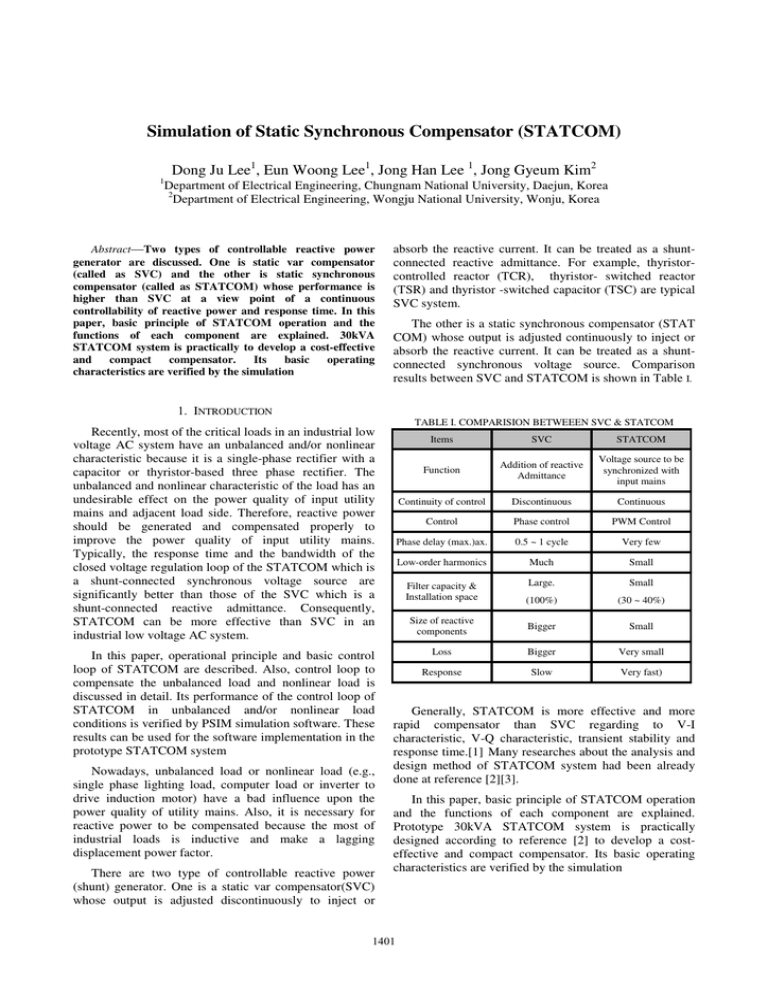
Simulation of Static Synchronous Compensator (STATCOM) 1 Dong Ju Lee1, Eun Woong Lee1, Jong Han Lee 1, Jong Gyeum Kim2 Department of Electrical Engineering, Chungnam National University, Daejun, Korea 2 Department of Electrical Engineering, Wongju National University, Wonju, Korea Abstract—Two types of controllable reactive power generator are discussed. One is static var compensator (called as SVC) and the other is static synchronous compensator (called as STATCOM) whose performance is higher than SVC at a view point of a continuous controllability of reactive power and response time. In this paper, basic principle of STATCOM operation and the functions of each component are explained. 30kVA STATCOM system is practically to develop a cost-effective and compact compensator. Its basic operating characteristics are verified by the simulation absorb the reactive current. It can be treated as a shuntconnected reactive admittance. For example, thyristorcontrolled reactor (TCR), thyristor- switched reactor (TSR) and thyristor -switched capacitor (TSC) are typical SVC system. The other is a static synchronous compensator (STAT COM) whose output is adjusted continuously to inject or absorb the reactive current. It can be treated as a shuntconnected synchronous voltage source. Comparison results between SVC and STATCOM is shown in Table I. 1. INTRODUCTION TABLE I. COMPARISION BETWEEEN SVC & STATCOM Recently, most of the critical loads in an industrial low voltage AC system have an unbalanced and/or nonlinear characteristic because it is a single-phase rectifier with a capacitor or thyristor-based three phase rectifier. The unbalanced and nonlinear characteristic of the load has an undesirable effect on the power quality of input utility mains and adjacent load side. Therefore, reactive power should be generated and compensated properly to improve the power quality of input utility mains. Typically, the response time and the bandwidth of the closed voltage regulation loop of the STATCOM which is a shunt-connected synchronous voltage source are significantly better than those of the SVC which is a shunt-connected reactive admittance. Consequently, STATCOM can be more effective than SVC in an industrial low voltage AC system. In this paper, operational principle and basic control loop of STATCOM are described. Also, control loop to compensate the unbalanced load and nonlinear load is discussed in detail. Its performance of the control loop of STATCOM in unbalanced and/or nonlinear load conditions is verified by PSIM simulation software. These results can be used for the software implementation in the prototype STATCOM system Nowadays, unbalanced load or nonlinear load (e.g., single phase lighting load, computer load or inverter to drive induction motor) have a bad influence upon the power quality of utility mains. Also, it is necessary for reactive power to be compensated because the most of industrial loads is inductive and make a lagging displacement power factor. There are two type of controllable reactive power (shunt) generator. One is a static var compensator(SVC) whose output is adjusted discontinuously to inject or Items SVC STATCOM Function Addition of reactive Admittance Voltage source to be synchronized with input mains Continuity of control Discontinuous Continuous Control Phase control PWM Control Phase delay (max.)ax. 0.5 ~ 1 cycle Very few Low-order harmonics Much Small Filter capacity & Installation space Large. Small (100%) (30 ~ 40%) Size of reactive components Bigger Small Loss Bigger Very small Response Slow Very fast) Generally, STATCOM is more effective and more rapid compensator than SVC regarding to V-I characteristic, V-Q characteristic, transient stability and response time.[1] Many researches about the analysis and design method of STATCOM system had been already done at reference [2][3]. In this paper, basic principle of STATCOM operation and the functions of each component are explained. Prototype 30kVA STATCOM system is practically designed according to reference [2] to develop a costeffective and compact compensator. Its basic operating characteristics are verified by the simulation 1401 2 PRINCIPLE OF STATCOM OPERATION A. System configuration Fig. 1(a) shows the basic configuration of STATCOM system. AC M AIN S Vs Is I inv 1 Link reactor (L1) V inv 1 DC Capacitor (C1) IL Voltage Source Inverter (with or without independently regulated dc source) LO A D As we know at equ. (1), there are two different methods of controlling the inverter output voltage to generate the leading or lagging reactive power from VSI. One is to change the dc capacitor voltage indirectly by controlling the phase angle between inverter output voltage and source voltage of utility mains. STATCOM without independently regulated dc source can be controlled by this method. The other is to control the modulation index of the inverter switching pattern directly while dc capacitor voltage is separately regulated well by another controller. STATCOM with independently regulated dc source can be controlled by this method. To achieve more fast dynamic response of reactive power compensation while dc capacitor voltage is regulated well, modulation index control for the required reactive power generation and phase angle control for the regulation of dc capacitor voltage can be done at the same time.[4] (a) Configuration Is 3 DESIGN OF STATCOM A. Design specification L1 Vs Design specification of 30kVA prototype STATCOM is shown in Table II. TABLE II. DESIGN SPECIFICATION Item Specification V in v 1 if V in v 1 > V s , I s = lead in g cu r r e n t if V in v 1 < V s , I s = lag g in g c u r r e nt (b) Single phase equivalent circuit Fig. 1. STATCOM system based on VSI STATCOM based on VSI (voltage source inverter) is a synchronous voltage source connected to the utility mains in parallel through a link reactor(L1) as shown in Fig. 1(a). Switching device can be GTO for high voltage, high power application or can be IGBT for low voltage, low power application. It is necessary to note that the size of dc capacitor in STATCOM is considerably smaller than the general ac capacitor for direct power factor compensation. 30kVA Rated input voltage 380/220V Rated input frequency 60Hz Total harmonic distortion of ac input current Less than 5% B. Design results Prototype 30kVA STATCOM system is designed to develop a cost-effective and compact compensator. Inductance and power rating of link reactor (L1) can be calculated by equ. (2) and equ. (3). Dc capacitor can be selected by equ. (4) and equ. (5) Design results are summarized in Table III. 4⋅ B. Injection and absorb of reactive power X L1 = As explained in Fig.1(b), inverter output voltage should be controlled to inject or absorb the reactive current on STACOM. Inverter output voltage of VSI can be generally expressed by equ. (1). Vinv _ peak = MI ⋅ Vdc Output power rating ∞ 1 n +1 ⋅ 2 ⋅ ∑ (−1) j +1 cos(k ⋅ α j ) − 1 4 j =1 ∑k k =5 π ⋅ MI ⋅ THDi − 4 ⋅ ∞ 1 ∑ 4 k =5 k 2 (2) n +1 ⋅ 2 ⋅ ∑ ( −1) j +1 cos(k ⋅ α j ) − 1 j =1 2 where, k : harmonic order αj : j th angle of switching pattern. (1) 2 where, Vinv _ peak : inverter output voltage(peak) [V], MI : modulation index of switching pattern, Vdc : dc capacitor voltage [V] 2 2 ⋅ Rf ⋅ Vdc X C1 = 3⋅ 1402 ( S L1 = X L1 ⋅ I s 1 + THDi ∞ 1 2 ⋅ (Ak −1 + Ak +1 ) 2 k k =6 ,12 ∑ ) (3) (4) Ak = respectively. Vsa is phase voltage of ac mains, Isa is phase current of ac mains and Ic is input current of dc capacitor It is verified in Fig. 3 that that STATCOM is being operated as a capacitor load or inductive load depend -ing on the operation mode (leading compensation or lagging compensation) 4 n +1 ⋅ 2 ⋅ ∑ ( −1) j +1 cos(k ⋅ α j ) − 1 (5) k ⋅ π k =1 where, Rf : ripple factor of dc capacitor. k : harmonic order (=6, 12….) Ak : Fourier coefficient of the switching pattern. TABLE III. DESIGN RESULTS Item Specification Link reactor 4.851 [mH], 3.8kVA dc capacitor 102 uF Peak current Peak reverse 767.8[V] blocking voltage Modulation index (MI) αj Isa 64.9 [A] of switching device Switching pattern ( Vsa ) Ic 1.12 4.4, 10.8, 14.1, 21.1, 23.4, 31.6, 33.0 , 42.3, 43.1, 65.0, 66.3, [Deg] (a) Lagging compensation mode 4 MODEL AND SIMULATION A. Simulation model Isa STATCOM system without indepe ndently regulated dc source is modeled for simulation as Fig. 2 and reactive power is generated by the phase angle control. Vsa Ic (b) Leading compensation mode Fig. 3. Simulation results 5 CONCLUSION In this paper, basic principle of STATCOM operation and the functions of each component are explained. 30kVA STATCOM system is practically designed and the basic operating characteristics are verified by the simulation. (a) Voltage source converter REFERENCES [1] N. G. Hingorani and L. Gyugyi,, "Understanding FACTS”, IEEE (b) dc voltage controller and reactive power controller Fig.. 2. Simulation model of 30kVA STATCOM B. Simulation results Lagging and leading compensation of the designed STATCOM system are shown in Fig. 3(a) and Fig. 3(b) Press, 1999. [2] Luis T. Moran, Phoivos D. Ziogas and Geza Joos, “Analysis and Design of a Three-Phase Synchronous Solid-state Var Compensator”, IEEE Trans. Ind. Appl., vol. 25, no.4 , pp. 598-608, July/Aug., 1989. [3] Hassan Ali Kojori, Shashi B. Dewan and J. Douglas Lavers, “A Large-Scale PWM Solid-State Synchronous Condenser”, IEEE Trans. on Ind. Appl., vol. 28, no. 1, Jan./Feb., 1992. [4] Guk C. Cho, Nam S. Choi, Chun T. Rim and Gyu H. Cho, “Modeling, Analysis and Control of Static VAR Compensator Using Three-Level Inverter”, IEEE Ind. Appl. Society Annual Meeting, pp. 837-843, 1992. 1403


