CHP Max Headend Optics Platform
CHP‐GMOD
1 GHz 1550 nm Externally Modulated Transmitters
FEATURES
• Reach more customers with intermediate (65 km) and long (100 km) range performance models
• Optimize link performance with adjustable SBS
• WDM and DWDM wavelength options
• Support Multiple Optical Architectures including Broadcast/ Narrowcast Overlay and RFoG
• Simplified installation and control with ARRIS CORView™ Element Management System solution
PRODUCT OVERVIEW
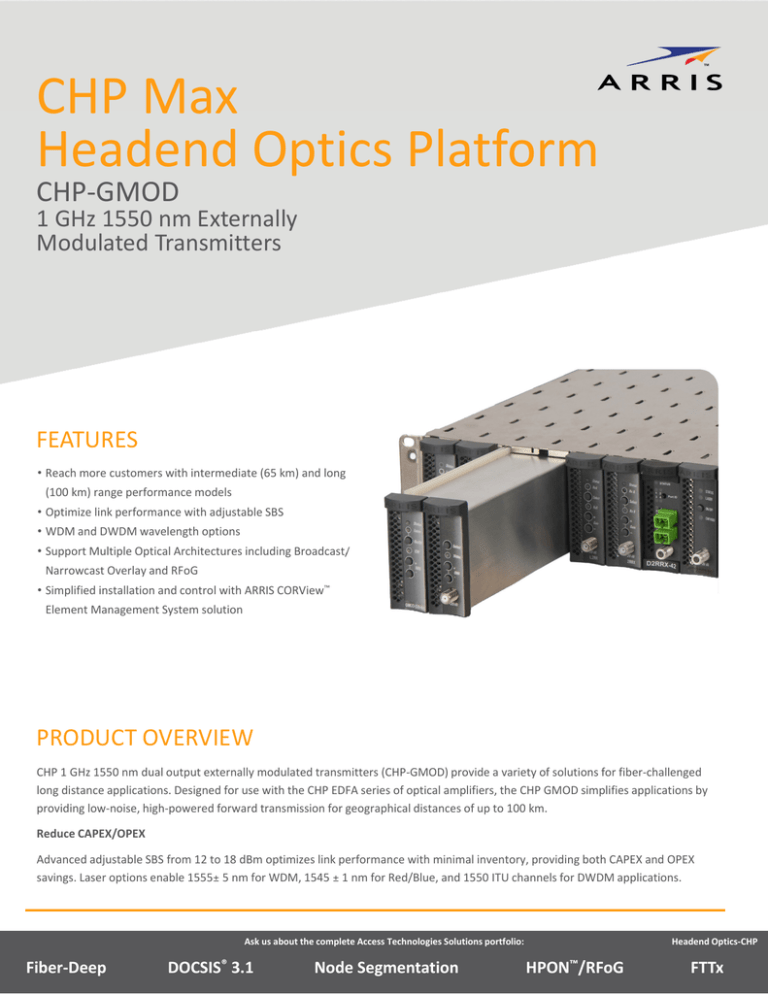
CHP 1 GHz 1550 nm dual output externally modulated transmitters (CHP‐GMOD) provide a variety of solutions for fiber‐challenged long distance applications. Designed for use with the CHP EDFA series of optical amplifiers, the CHP GMOD simplifies applications by providing low‐noise, high‐powered forward transmission for geographical distances of up to 100 km. Reduce CAPEX/OPEX
Advanced adjustable SBS from 12 to 18 dBm optimizes link performance with minimal inventory, providing both CAPEX and OPEX savings. Laser options enable 1555± 5 nm for WDM, 1545 ± 1 nm for Red/Blue, and 1550 ITU channels for DWDM applications. Ask us about the complete Access Technologies Solutions portfolio:
Fiber‐Deep
DOCSIS® 3.1
Node Segmentation
Headend Optics‐CHP
HPON™/RFoG
FTTx
CHP‐GMOD Conserve Footprint, Add New Services
The CHP Max5000® headend chassis can accommodate up to five double‐width CHP‐GMODs (for a total of up to 100 double‐width modules in a standard 40RU rack) to reduce footprint as operators expand services. CHP‐GMODs are hot‐swappable and can be monitored through the CORView™ Element Management Software or CHP Craft GUI. Remote management is accessible through the SNMP HMS‐compliant interface for external connection to an element management system. OPTIONS
Advanced 1 GHz technology and adjustable SBS from 12 to 18 dB for maximum performance and minimal inventory
Laser options support standard 1555 +/– 5 nm, 1545 +/– 1 nm, and DWDM for various fiber challenged applications
APPLICATIONS
100km Single Channel Application
Ask us about the complete Access Technologies Solutions portfolio:
Fiber‐Deep
DOCSIS® 3.1
Node Segmentation
Headend Optics‐CHP
HPON™/RFoG
FTTx
CHP‐GMOD SPECIFICATIONS
RF
Bandwidth
40 to 1002 MHz
Input Power
39 ± 3 dBmV total power
23 dBmV/channel @ 40 NTSC channels
20 dBmV/channel @ 80 NTSC channels
18.5 dBmV/channel @ 112 NTSC channels
Flatness
Without EDC:
With EDC:
± 0.5 dB, max. 40 to 879 MHz; ± 0.75 dB, max. 40 to 1002 MHz
± 0.5 dB, 40 to 550 MHz; ± 0.75 dB, 40 to 1002 MHz
Impedance
75Ω
Return Loss
17 dB, min., all ports (40 to 870 MHz)
16 dB min., all ports (870 to 1002 MHz)
Residual Spurs
< 65 dBc
Number of Inputs
1
Common Optical
Wavelength
1545 ± 1 nm; 1555 ± 5 nm; ITU channels 21, 23, 25, 27, 29, 39
Line Width, max.
0.6 MHz
Output Power, Ports 1 and 2
8 dBm
Laser RIN
< –157 dBc/Hz
Return Loss
> 55 dB
Modulation Index
3% min. per channel / 80 channels
SBS Suppression
Variable 12 dB to 18 dB
Number of Outputs
2
Medium Haul Performance 1
80/112 NTSC Channel Loading +300 Split Band 40 Low/40 High NTSC Ch. MHz QAM to 870 MHz (450 MHz QAM for 40 NTSC +300 MHz QAM to 870 to 1002 MHz) 2, 3, 5, 6
MHz (450 MHz QAM to 1002 MHz) 2, 3, 7
Link Budget
65 km
Split Band 60 Low/20 High NTSC Ch. for 60 NTSC +450 MHz QAM to 1002 MHz 2, 4, 8
65 km
50 km
Channels
80
112
40 low
40 high
60 low
20 high
CNR
52.5 (51.5) dB
51 (50) dB
55.2 (54) dB
55.2 (54) dB
54.5 dB
54.5 dB
CTB
–66 dBc
–66 dBc
–70 dBc
–70 dBc
–68 dBc
–68 dBc
CSO
–66 dBc
–66 dBc
–70 dBc
–70 dBc
–69 dBc
–69 dBc
XMOD, max.
–66 dBc
–66 dBc
–70 dBc
–70 dBc
–70 dBc
–70 dBc
Ask us about the complete Access Technologies Solutions portfolio:
Fiber‐Deep
DOCSIS® 3.1
Node Segmentation
Headend Optics‐CHP
HPON™/RFoG
FTTx
CHP‐GMOD SPECIFICATIONS (CONTINUED)
Low Haul Performance 1
80/112 NTSC Channel Loading +300 MHz QAM to 870 MHz (450 MHz QAM to 1002 MHz) 2, 3, 5, 9
Split Band 40 Low/40 High NTSC Ch. Split Band 60 Low/20 High NTSC Ch. for 40 NTSC +300 MHz QAM to 870 for 60 NTSC +450 MHz QAM to 1002 2, 3, MHz (450 MHz QAM to 1002 MHz) MHz 2, 4,11
10
Link Budget
100 km
100 km
90 km
Channels
80
112
40 low
40 high
60 low
20 high
CNR
49.8 (48.8) dB
47.5 (46.5) dB
52.3 (51.3) dB
52.3 (51.3) dB
52.5 (51.5) dB
52.5 (51.5) dB
CTB
–66 dBc
–65 dBc
–70 dBc
–70 dBc
–68 dBc
–68 dBc
CSO
–65dBc (with EDC)
–65dBc (with EDC)
–70 dBc
–70 dBc
–69 dBc
–69 dBc
XMOD, max.
–66 dBc
–66 dBc
–70 dBc
–70 dBc
–70 dBc
–70 dBc
Powering
Power Consumption
40 W, max.; 12 V at 1.6 A, max.
Physical and Environmental
Dimensions (W x H X D), double‐width module:
6.35 x 8.7 x 43.87 cm (2.5 x 3.4 x 17.27 in)
Operating Temperature Range:
0 to 50°C (32 to 122°F)
Operating Humidity, non‐condensing:
10 to 90%
Notes:
1. Specifications are worst case and are for both output ports. Reference receiver: 7 pA/Hz0.5. Reference receiver input: 0 dBm. SBS suppression: 12 to 18 dBm. GMOD performance is no worse than CTB performance as specified per the channel plan.
2. Specifications are based on a reference receiver.
3. Reference maximum channel loading: QAM channel loading is –6 dBc relative to analog carriers.
4. Reference maximum channel loading: QAM channel loading is –2 dBc relative to analog carriers.
5. 64 PAL channel performance is equivalent to 80 NTSC channel performance. 42 CENELEC channel CSO and CTB performance is equivalent to 80 NTSC channel performance. 42 CENELEC channel CNR performance is 1.0 dB higher than 80 NTSC channel performance.
6. 16 dBm EDFA, 65 km fiber, 0 dBm at receiver.
7. 16 dBm EDFA, 65 km fiber, 2 dBm at receiver.
8. 16 dBm EDFA, 65 km fiber, 3 dBm at receiver.
9. 16 dBm EDFA, 45 km fiber, 16 dBm EDFA, 55 km fiber, 0 dBm at receiver.
10.16 dBm EDFA, 45 km fiber, 16 dBm EDFA, 55 km fiber, 2 dBm at receiver.
11.16 dBm EDFA, 45 km fiber, 16 dBm EDFA, 55 km fiber, 3 dBm at receiver.
RELATED PRODUCTS
CHP Chassis
Optical Patch Cords
Power Supplies
Optical Passives
Control Module
Installation Services
Note: Specifications are subject to change without notice.
Copyright Statement: ©ARRIS Enterprises, Inc. 2015 All rights reserved. No part of this publication may be reproduced in any form or by any means or used to make any derivative work (such as translation, transformation, or adaptation) without written permission from ARRIS Enterprises, Inc. (“ARRIS”). ARRIS Customer Care
reserves the right to revise this publication and to make changes in content from time to time without obligation on the part of ARRIS to provide notification of such revision or change. ARRIS and the ARRIS logo Contact Customer Care for product information and sales:
• United States: 866‐36‐ARRIS
• International: +1‐678‐473‐5656
are all registered trademarks of ARRIS Enterprises, Inc. Other trademarks and trade names may be used in this document to refer to either the entities claiming the marks and the names of their products. ARRIS disclaims proprietary interest in the marks and names of others. The capabilities, system requirements and/or compatibility with third‐party products described herein are subject to change without notice.
(rev 12-2014)
CHP‐GMOD_DS_01DEC14
Ask us about the complete Access Technologies Solutions portfolio:
Fiber‐Deep
DOCSIS® 3.1
Node Segmentation
Headend Optics‐CHP
HPON™/RFoG
FTTx


