This paper has been submitted for journal paper peer review
1
Multiple-Symbol Interleaved RS Codes and
Two-Pass Decoding Algorithm
Z. Wang, A. Chini, M. Kilani, and J. Zhou
Broadcom Corp., California, 92617, USA
Abstract — For communication systems with heavy burst noise,
an optimal Forward Error Correction (FEC) scheme is expected
to have a large burst error correction capacity while
simultaneously owning moderate random error correction
capability. This letter presents a new FEC scheme based on
multiple-symbol interleaved Reed-Solomon codes and an
associated two-pass decoding algorithm. It is shown that the
proposed multi-symbol interleaved coding scheme can achieve
nearly twice as much as the burst error correction capability of
conventional symbol-interleaved Reed-Solomon codes with the
same code length and code rate.
Index Terms — burst-interleaved, erasure decoding, FEC,
multi-symbol interleaved, Reed-Solomon codes.
I. INTRODUCTION
T
WO important error types present in most digital
communication systems are random and burst errors.
Random errors are typically the result of independent error
events and are scattered. Burst errors are the result of correlated
noise events and appear in clusters. In some applications, such
as automotive networks with high level interference from
adjacent systems, burst noise is much more prominent than
random noise. In such situations, an optimal FEC scheme is
expected to have a large Burst Error Correction Capability
(BECC) while owning moderate Random Error Correction
Capability (RECC) at the same time. Most of the existing FEC
schemes are designed for heavy random errors that are
inefficient in dealing with burst errors [1], [2].
Interleaved Reed-Solomon (IRS) codes were proposed when
both large RECC and BECC are emphasized [3], [4]. The IRS
codes integrate a high RECC of RS codes with interleaving
techniques to improve BECC. An IRS code usually consists of
several independent RS codes with the same code length.
Depending on the codeword dimension, homogeneous and
heterogeneous IRS codes were developed with their associated
decoding algorithms, such as shift-register synthesis-based
joint decoding method [5] and interpolation-based probabilistic
decoding algorithm [6].
Existing IRS schemes interleave the independent RS coders
at single-symbol level and adopt a single-pass decoding
method. In this letter, we present a novel IRS code. The
codewords are interleaved at the multiple-symbol level and a
two-pass decoding algorithm is used. Without knowing burst
Authors are with Infrastructure & Networking Group, Broadcom Corp.,
California, 92617, USA. (e-mail: zfwang88@gmail.com).
error locations, the proposed Multiple Symbol IRS (MS-IRS)
scheme (or burst-interleaved RS coding), can achieve nearly
twice as much as the BECC of conventional Single Symbol IRS
(SS-IRS) codes with the same code length and code rate. In
addition, the BECC and processing latency of the proposed
MS-IRS codes can be optimized by adjusting the length of each
independent RS codes. A two-pass decoding algorithm is
presented to enable the increased BECC of MS-IRS schemes.
Specifically, in the first pass, one or more independent RS
codes are decodable if the length of burst errors corrupting a
specific RS code is smaller than the error correction capability
of the code. An approximate burst error location can be derived
from the corrected codewords in the first pass and then a second
pass decoding will be performed with combined error and
erasure coding [7], which improves the BECC.
This letter is organized as follows. Section II introduces the
MS-IRS encoding scheme. Theoretical BECC and decoding
latency are studied. Section III presents the proposed two-pass
decoding algorithm. Monte-Carlo simulations on an example
channel are presented in Section IV.
II. MS-IRS CODES
Assume IRS codes with an interleaving depth equals to L.
Each independent RS code is denoted by RS(N, K, m), where N
is the number of symbols in a codeword, K is the number of
source data symbols in a codeword, and m is the number of bits
in each symbol. The burst-length (denoted as BL) refers to the
number of symbols in each dispatch of data to one component
code. Fig.1 illustrates the block diagram of a general IRS codes
encoding scheme. A DEMUX splits the source data and feeds
one of L independent RS encoders at each instant. A MUX
combines the encoders output back into one data stream.
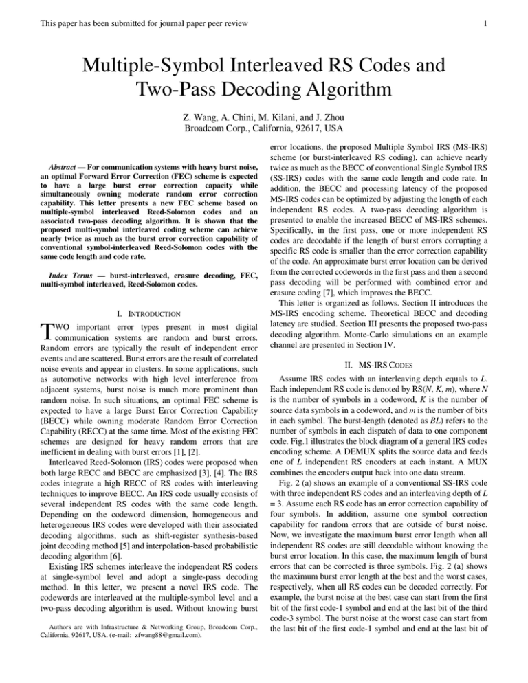
Fig. 2 (a) shows an example of a conventional SS-IRS code
with three independent RS codes and an interleaving depth of L
= 3. Assume each RS code has an error correction capability of
four symbols. In addition, assume one symbol correction
capability for random errors that are outside of burst noise.
Now, we investigate the maximum burst error length when all
independent RS codes are still decodable without knowing the
burst error location. In this case, the maximum length of burst
errors that can be corrected is three symbols. Fig. 2 (a) shows
the maximum burst error length at the best and the worst cases,
respectively, when all RS codes can be decoded correctly. For
example, the burst noise at the best case can start from the first
bit of the first code-1 symbol and end at the last bit of the third
code-3 symbol. The burst noise at the worst case can start from
the last bit of the first code-1 symbol and end at the last bit of
This paper has been submitted for journal paper peer review
Encoder-1
Encoder-L
Ctrl-1
Ctrl-2
Fig. 1. Block diagram of a general IRS codes encoding scheme.
BL=1, Best Case
1
2
3
1
2
3
1
2
3
1
2
3
1
2
3
1
2
3
BL=1, Worst Case
(a)
BL=3, Best Case
1
2
3
1
2
3
BL=3, Worst Case
(b)
Fig. 2. An illustration of the maximum burst error length at the best and worst
cases when all codes can be decoded correctly. Interleaved depth is 3. (a)
SS-IRS codes, BL=1; (b) MS-IRS codes BL=3 with two-pass decoding
algorithm.
Start
K=0
De-Interleaving
RS Decoding
None
Any Block
Corrected ?
Y
Y
All Blocks
Corrected ?
K = K+ 1
N
III. TWO-PASS DECODING ALGORITHM
To achieve the increased BECC in the MS-IRS codes, we
propose a two-pass signal decoding algorithm. Fig. 3 illustrates
the flow diagram of the proposed two-pass signal decoding
algorithm. In the first pass, perform RS decoding as usual and
checks if at least one RS code can be decoded. Based on the
decoding result, we can determine the burst error location and
predict the erasure starting segment when at least one RS code
is decodable. In this case, erasure decoding (or combined error
and erasure decoding [7] when burst length BL is smaller than
error correction length t) will be performed in the second pass
of error decoding. Therefore, a longer burst of errors can be
corrected.
Encoded
Data
MUX
Encoder-2
DEMUX
Source
Data
...
the third code-3 symbol.
Fig. 2 (b) shows an example of an MS-IRS code also with L
= 3 and the length of each burst interleaving is 3-symbol (i.e.,
BL = 3). Similar to Fig. 2 (a), the maximum burst noise length at
the best and the worst cases are shown with one symbol error
correction capability reserved for random errors. Adopting the
proposed two-pass decoding algorithm, we need to decode at
least one RS code correctly in the first pass. In the case shown
in Fig. 2(b), the code-3 is decodable if the length of burst error
is not too long. The burst noise at the best case can start from
the first bit of the first code-1 symbol group and end at the last
bit of the second code-2 symbol group. The burst noise in the
worst case can start from the last bit of the first code-1 symbol
group (or code-1 segment) and end at the last bit of the second
code-2 symbol group.
In general, assume each RS code has an error correction
capability of t symbols over GF(2m). Without knowing the burst
noise locations, the SS-IRS and MS-IRS codes have a BECC of
(L*t-1)*m+1 bits and (L-1)*2t*m+1 bits at the worst case,
respectively. It means that MS-IRS codes achieve nearly twice
of the BECC of conventional SS-IRS codes when L is large.
For MS-IRS codes, the above BECC equation assumes the
number of symbols in each colored segment is equal to t, i.e.,
BL=t. If the number of symbols in each colored segment is less
than t, a combination of random and burst errors can be
corrected. Then, the BECC is equal to (L-1)*2BL*m+1 bits, in
this case. In general, we choose BL such that 2BL>>t>BL in
order to achieve good tradeoff between BECC and RECC.
We now calculate the encoding and decoding latency of the
MS-IRS codes. At the transmitter, a data buffer is needed to
accommodate for increased data rate after FEC. The buffering
latency is calculated based on the total FEC block and parity
size. At the receiver, latency includes receiving time for the
interleaved code plus decoding latency. For example, given a
RS code (108, 96, t=6) over GF(29) and 4X interleaving with
BL = 5, and assuming 1Gbps of data rate, the buffering latency
is 4*(108-96)*96/108*9*1ns = 384ns. The receiving latency is
4*96*9*1ns = 3456ns. Decoding latency can be less than 120ns.
Therefore, the total latency associated with FEC is less than
4µs.
2
Stop
Y
K=1
N
Identify The case
Find Error Locations
of Blocks in Error
Fig. 3. Flow chart of the two-pass MS-IRS codes decoding algorithm.
IV. SIMULATIONS
In this section, the advantage of the proposed MS-IRS code
is verified by simulating an example communication system
with PAM3 modulation scheme. The block diagram of the
system model is shown in Fig. 4. The short RS code blocks are
This paper has been submitted for journal paper peer review
TABLE I
MAPPING TABLE
000
001
Symbol Bits
Mapper Output
{even, odd}
Symbol Bits
Mapper Output
{even, odd}
{-1,-1}
{-1,0}
010
011
{-1,+1}
{0,-1}
100
101
110
111
{0,+1}
{+1,-1}
{+1,0}
{+1,+1}
Transmitter
Random
Integer
Channel
RS
Encoder
DFE
Equalizer
Interleaver
DeMapper
Mapper
Deinterleaver
RS
Decoder
Receiver
Fig. 4. Simulation model block diagram.
Amplitude
burst interleaved in the interleaver block, whereas for the long
RS code, the interleaver is not applied. The output of the RS
encoder and the interleaver is applied to a mapper that maps the
symbols (3 bits each) to physical layer values {-1, 0, +1}. The
method of mapping is given in Table I. The physical layer
symbols {-1, 0, +1} are then transmitted.
The channel is assumed to be real valued and the imaginary
and the real parts of symbols at the mapper output are
transmitted as the even and odd samples. The channel response
is depicted in Fig. 5. It is seen that the channel is dispersed over
several physical layer symbols, which results in severe Inter
Symbol Interference (ISI). To remove the ISI, a Decision
Feedback Equalizer (DFE) is used at the receiver. The block
diagram of the channel, noises, and the receiver equalizer (DFE)
are shown in Fig.6. Note that it is assumed that the channel
response is known to the receiver. The slicing is performed in
one dimensional form as soon as one symbol is received; it is
compared against a threshold (±0.5) and accordingly is selected
from the set {-1,0,-1}. Once a pair of even and odd are collected,
the symbol bits are obtained by demapper (see Table I).
Normally the RS decoder is able to correct the errors during
the burst duration. In practice, however, the number of errors is
more than the number of symbols corrupted by the burst noise.
This is due to the error propagation problem associated with the
DFE in which when the slicer makes a few decisions, the errors
propagate through the feedback filter and arrive at the slicer
input causing more errors to occur. These errors are bursty in
nature and could easily extend to a number beyond the error
correction capability of RS codes. In the following simulation
cases, it will be shown that short RS codes, when followed by a
multi-symbol interleaver, significantly improve the
performance when compared with long RS codes.
3
Symbol Number
Fig.5. Channel response.
A. Case 1
This case compares a long code RS(N=432, K=387, t=22,
m=9) L=1, with a short code RS(N=144, K=129, t=7, m=9) that
has been multi-symbol interleaved with parameters L=3 and
BL=6. The channel noises are assumed to be AWGN with
Signal-to-Noise Ratio (SNR) of 30dB and a burst noise. The
burst duration and period are set equal to 38 symbols and 5400
symbols, respectively. The Bit Error Rate (BER) and Block
Error Rate vs. the Signal to Burst Ratio (SBR) are shown in
Fig.7 and Fig.8, respectively. It is seen that the short RS code
with multi-symbol interleaver with single pass exhibits a very
similar performance to the long RS code. But, it is clear that
RS(144,129) with a multi-symbol interleaver (L=3, BL=6)
when used with a two-pass decoder performs significantly
better than RS(432,387)
B. Case 2
In this case, RS(N=147, K=132, t=7, m=9), L=3, BL=7, is
compared against RS(N=144, K=129, t=7, m=9), L=3, BL=6,
under the same channel conditions as given in Case 1, except
that the burst duration is increased to 114 symbols. The BER
and Block Error Rate vs. the SBR are shown in Fig.9 and Fig.
10, respectively. It is seen that RS(N=147, K=132, t=7, m=9),
L=3, BL=7 performs better than RS(N=144, K=129, t=7, m=9),
L=3, BL=6. In other words, depending on the burst noise
duration and severity of the burst error, the BL value can be
selected in such a way that the best performance can be
achieved without necessarily increasing the RS code length and
latency.
V. CONCLUSIONS
In this letter, we have introduced the multi-symbol
interleaving scheme, specifically multi-symbol interleaved RS
coding, together with a two-pass decoding algorithm. The
guidance about selecting interleaving parameters is given, and
the detailed simulation results demonstrated the benefits of the
proposed coding method. It should be noted that the component
codes can also be BCH, LDPC, or other FEC codes.
This paper has been submitted for journal paper peer review
AWGN
Burst noise
+
+
Σ
D
Slicer
-
+
h1
4
Σ
h2
h32
h32
D
D
D
h2
D
h1
D
Fig. 6. The channel and receiver Equalizer block diagram.
Fig. 9. Bit Error Rate vs. Signal to Burst Noise Ratio for short RS code but
different burst length (Blue line BL=7, Red line BL=6).
UnCoded
RS(144,129) + Single Pass
RS(432,387)
RS(144,129) + Two Pass
Fig. 7. Bit Error Rate vs. Signal to Burst Noise Ratio (Case 1).
Fig. 10. Block Error Rate vs. Signal to Burst Noise Ratio for short RS code but
different burst length (Blue line BL=7, Red line BL=6).
UnCoded
RS(144,129) + Single Pass
RS(432,387)
RS(144,129) + Two Pass
[3]
[4]
Fig. 8. Block Error Rate vs. Signal to Burst Noise Ratio (Case 1).
[5]
[6]
REFERENCES
[1]
[2]
S. Lin, D. J. Costello, Error Control Coding, 2nd Edition, Pearson-Prentice
Hall, Jun. 2004.
T. K. Moon, Error Correction Coding: Mathematical Methods and
Algorithms, Wiley-Interscience, Jun. 2005.
[7]
V. Y. Krachkovsky, “Reed–solomon codes for correcting phased error
bursts,” IEEE Trans. Information Theory, vol. 49, no. 11, pp:2975–2984,
Nov. 2003.
V. Y. Krachkovsky, Y. X. Lee, “Decoding for iterative Reed–Solomon
coding schemes,” IEEE Trans. Magnetics, vol. 33, no. 5, pp: 2740–2742,
Sep. 1997.
G. Schmidt, V. R. Sidorenko, M. Bossert, “Collaborative decoding of
interleaved Reed–Solomon codes and concatenated code designs,” IEEE
Trans. Information Theory, vol. 55, no.7 , pp: 2991–3012, Jul. 2009.
D. Coppersmith, M. Sudan, “Reconstructing curves in three (and higher)
dimensional space from noisy data,” in Proceedings of the Thirty-Fifth
Annual ACM symposium on Theory of computing, STOC ’03, pp. 136–
142. ACM, New York, 2003.
L. Li, B. Yuang, Z. Wang, J. Sha, H. Pan, and W. Zheng, “Unified
Architecture for Reed-Solomon Decoder Combined With Burst-Error
Correction,” IEEE Trans. on VLSI Systems, vol. 20, no. 7, pp: 1346–1350,
Jan. 2012.


