Get Notes - Mindset Learn
advertisement

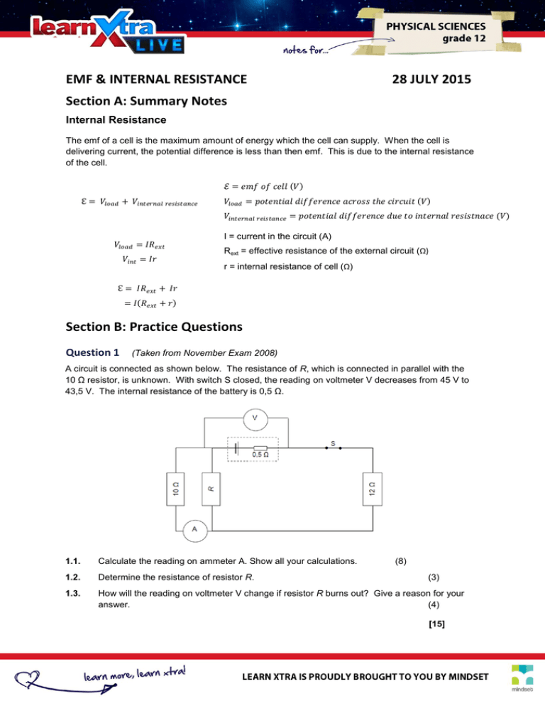
EMF & INTERNAL RESISTANCE 28 JULY 2015 Section A: Summary Notes Internal Resistance The emf of a cell is the maximum amount of energy which the cell can supply. When the cell is delivering current, the potential difference is less than then emf. This is due to the internal resistance of the cell. I = current in the circuit (A) Rext = effective resistance of the external circuit (Ω) r = internal resistance of cell (Ω) Section B: Practice Questions Question 1 (Taken from November Exam 2008) A circuit is connected as shown below. The resistance of R, which is connected in parallel with the 10 Ω resistor, is unknown. With switch S closed, the reading on voltmeter V decreases from 45 V to 43,5 V. The internal resistance of the battery is 0,5 Ω. 1.1. Calculate the reading on ammeter A. Show all your calculations. (8) 1.2. Determine the resistance of resistor R. 1.3. How will the reading on voltmeter V change if resistor R burns out? Give a reason for your answer. (4) (3) [15] Question 2 (Taken from Feb – March Exam 2009) The battery in the circuit below has an emf of 12 V and an internal resistance of resistance of the connecting wires can be ignored. 0,2 Ω. The 2.1. Calculate the current, I, that flows through the battery. (6) 2.2. How will the reading on the voltmeter be affected if the 9 Ω resistor is removed and replaced with a conducting wire of negligible resistance? Explain your answer. (4) [10] Question 3 (Taken from Gauteng Preparatory Exam 2009) The following circuit diagram shows a battery consisting of four 1,5 V cells connected in series. An ammeter with negligible resistance is connected in series to the battery. The reading on the ammeter is 0,5 A when the switch is closed. The connectors have negligible resistance and the voltmeters have very high resistance. Voltmeter V1 has a reading of 5,5 V when the switch is closed. 3.1 Calculate the value of the internal resistance of a single cell. (4) 3.2 Calculate the value of the resistance of the external circuit. (4) 3.3 Calculate the value of the reading on voltmeter V2. (4) Question 4 (Taken from Feb – March Exam 2010) The circuit diagram below shows a battery, with an internal resistance r, connected to three resistors, M, N and Y. The resistance of N is 2 Ω and the reading on voltmeter V is 14 V. The reading on ammeter A1 is 2 A and the reading on ammeter A2 is 1A. (The resistance of the ammeters and the connecting wire may be ignored) 4.1. State Ohm’s law in words. 4.2. How does the resistance of M compare with that of N? Explain how you arrived at the answer. (2) 4.3. If the emf of the battery is 17 V, calculate the internal resistance of the battery. (5) 4.4. Calculate the potential difference across resistor N. (3) 4.5. Calculate the resistance of Y. (4) (2) [16] Question 5 (Taken from November Exam 2010) The headlights of a car are connected in a parallel to a 12 V battery, as shown in the simplified circuit diagram below. The internal resistance of the battery is 0,1 Ω and each headlight has a resistance of 1,4 Ω. The starter motor is connected in parallel with the headlights and controlled by the ignition switch, S2. The resistance of the connecting wires may be ignored. 8.1. State Ohm’s law in words. 5.1. With only switch S1 closed, calculate the following: 5.2. (2) 5.1.1. Effective resistance of the two headlights. (3) 5.1.2. Potential difference across the two headlights. (4) 5.1.3. Power dissipated by one of the headlights. (3) Ignition switch S2 is now closed (whilst S1 is also closed) for a short time and the starter motor, with very low resistance, rotates. How will the brightness of the headlights be affected while switch S2 is closed? Write down only INCREASES, DECRESASES or REMAINS THE SAME. Fully explain how you arrived at the answer. (4) [16] Section C: Solutions Question 1 1.1. (8) 1.2. (3) 1.3. Increases The total resistance increases Therefore the current decreases Thus Vinternal decreases And reading on V increases (4) Question 2 2.1. (6) 2.2. Decreases Effective resistance of the circuit decreases Current increases And Vint (Ir) increases (4) Question 3 3.1. (4) 3.2. = (4) 3.3. (4) Independent variable: The type of element Dependent variable: Time taken to boil the water (2) Question 4 4.1. The current through a conductor is directly proportional to the potential difference across its ends at constant temperature. 4.2. (2) Equal 2 A divides equally at in the parallel section (IM = 1A then IN = 1 A) (2) 4.3. (5) 4.4. (3) 4.5. (4) Question 5 5.1. The current through a conductor is directly proportional to the potential difference across its ends at constant temperature. (2) 5.2.1. (3) 5.2.2. (4) 5.2.3. (3) 5.3. Decreases Total resistance decreases Therefore total current increases Vinternal (Vint = Ir) increases, thus potential difference across headlights decreases ( decreases) (4)


